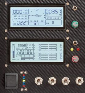
EFIS Overview
This new version of EFIS and EMS is primarily based on Arduino controllers and designed as an Open Architecture system. All the subsystems have been built to be as independent as practically possible and interconnected via standard CAN-Bus interface. This architecture also allows to upgrade/evolve the units independently and add the new units without affecting the ones that were installed previously.
The system is built of components and pre-assembled units readily available from various online electronics stores. The system is also reasonably easy to put together and can be easily customized.
All schematics and software along with detailed instructions are available for download from this site free of charge. (Your donations are highly appreciated)
Main components (subsystems)
- Display Unit based on Arduino Mega 2560 Pro Mini
- AHRS Unit – Gyro and Compass sensors – based on Arduino Nano and BNO055
- Module-A – Altitude, Airspeed and AoA sensors – based on Arduino Nano
- EMS Sensor Board – various engine sensors – based on Arduino Nano
- Flight Data Recorder – multifunctional unit providing GPS data, ADS-B In, aural warnings etc, – based on Raspberry Pi
- Power Supply for Can Bus interconnection board providing main power as well as backup power to EFIS.
The system uses unified Display Unit that can display both Flight and Engine information. Any number of Display Units can be attached to the system, making it very flexible and fault tolerant.
EFIS Functions and Features
The system monitors, collects and displays the following flight information:
| Function or Feature | EFIS Unit |
| Indicated Airspeed | Module-A |
| True Airspeed | Module-A |
| Ground Speed | FDR |
| Outside Air Temperature | Module-A |
| Altitude | Module-A |
| Vertical Speed | Module-A |
| Angle of Attack | Module-A |
| Magnetic Heading | AHRS |
| Ground Track | FDR |
| GPS Altitude | FDR |
| Artificial Horizon (Attitude) | AHRS |
| Load Factor | AHRS |
| Clock (UTC or Local) | Display Units |
| Flight Time (Airswitch) | Display Units |
| ADS-B IN (Traffic information) | FDR |
| RPM | EMS |
| EGT | EMS |
| CHT | EMS |
| Engine Time | EMS |
| Oil Temperature and Pressure | EMS |
| Fuel Pressure | EMS |
| Fuel Level | EMS |
| Main Electric Bus voltage | EMS |
| Battery charge/discharge current | EMS |
| Alternator current | EMS |
| Backup battery status | Module-A |
| Flight Data Recording | FDR |
The system also controls warning lights and provides aural warning via intercom.
All the parameters are recorded at configurable intervals by FDR in CSV file for flight analysis.
All the units except FDR are Arduino based – Display Unit uses Arduino Mega, the rest use Arduino Nano.
FDR unit is based on Raspberry Pi. It allows a lot of functionality that would be hard to do on Arduino, such as WiFi gateway, Aural Warnings, ADS-B etc. Most of the software for this unit is written on Python and is easily modified if required.
The interface to a tablet is based on Node.js – lightweight web server. It allows to display information of any mobile device (iPad or Android tablet) via web browser.
All the software is available for download from GitHub https://github.com/ExperimentalAvionics
Please note that this is project is constantly evolving. Features are improving and new functionality is being added.
