EFIS AHRS ver. 2.0
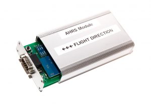 Attitude and Heading Reference System module

Updated 20 May 2020
The main idea of having this module separate from the rest of this avionics is to keep it away from the electromagnetic interference (EMI) of nearby circuits.
Magnetometer in the BNO055 chip is very sensitive and sometimes it gets confused by the EMIs.
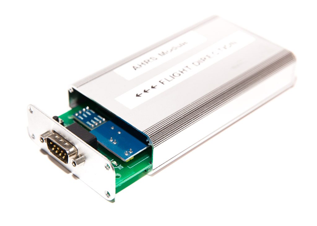
The module needs to be mounted inside an aluminium enclosure and installed somewhere away from other electric circuits, ideally close to the center of gravity of the aircraft.
The module is connected to the rest of the system via CAN-bus (CAN-HUB) that also provides the power to this unit.
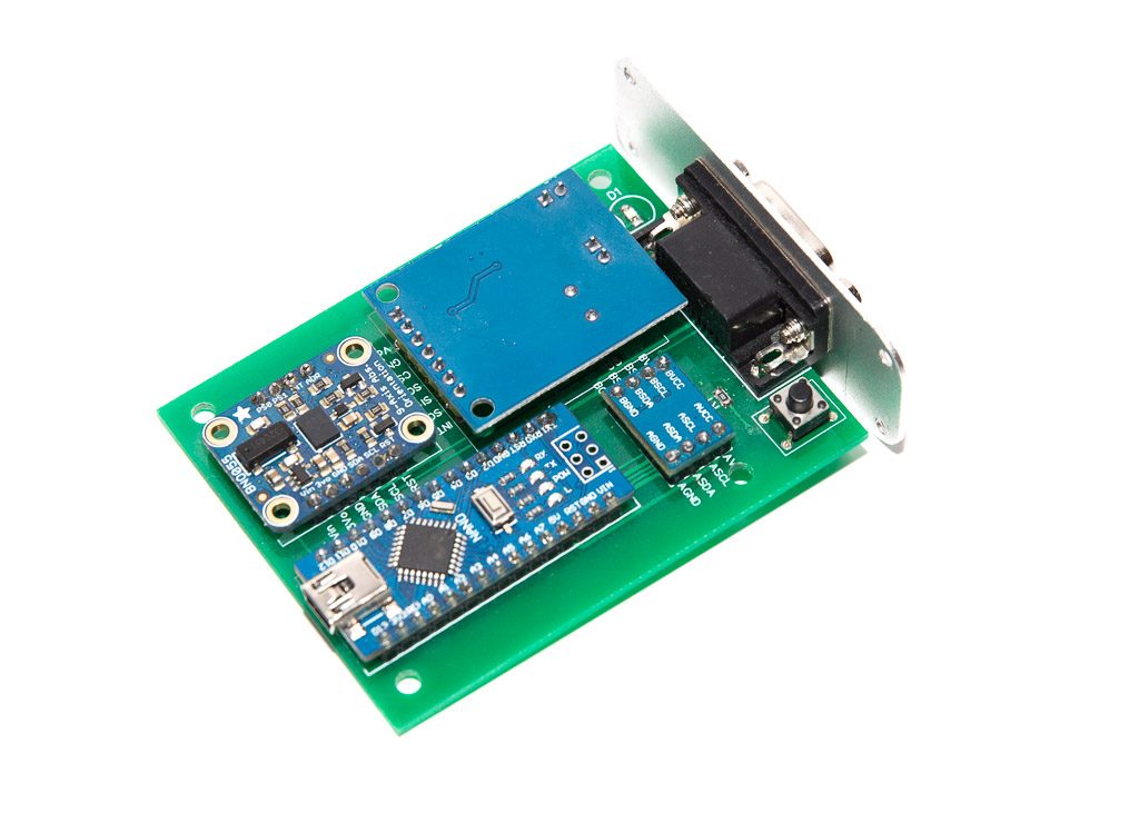
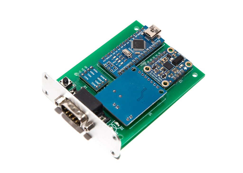
Parts list:
| Schematics Reference | Part Name |
 Arduino Nano (Available in our Store) Arduino Nano (Available in our Store) | |
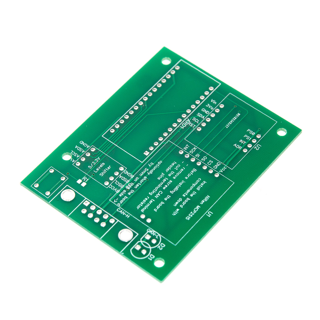 AHRS Module PCB Board (Available in our Store) AHRS Module PCB Board (Available in our Store) | |
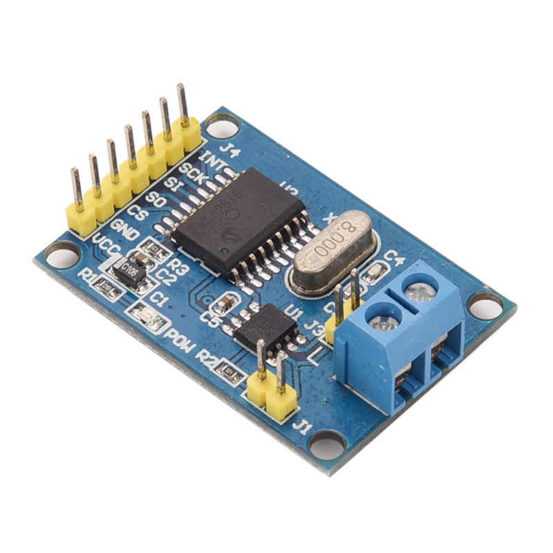 NiRen-MCP2515 CAN-Bus adapter (8Mhz) (Available in our Store) NiRen-MCP2515 CAN-Bus adapter (8Mhz) (Available in our Store) | |
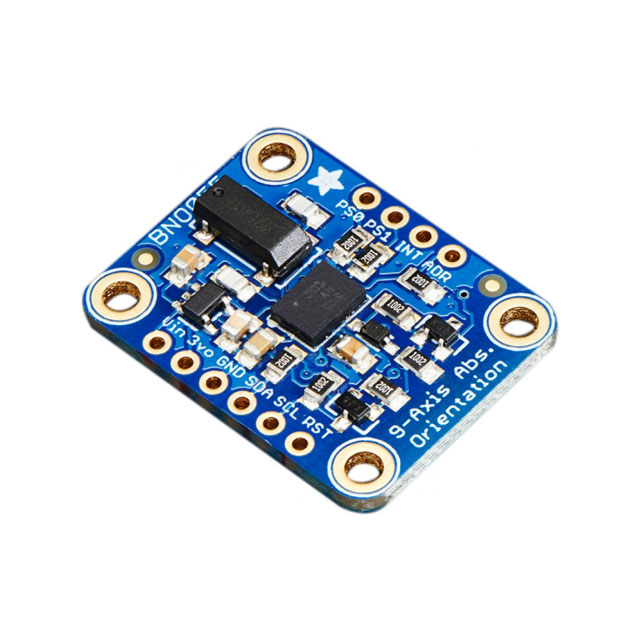 Adafruit BNO055 Absolute Orientation Sensor Adafruit BNO055 Absolute Orientation Sensor | |
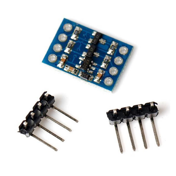 5v – 3v Logic Converter I2C. (Level Shifter) 5v – 3v Logic Converter I2C. (Level Shifter) | |
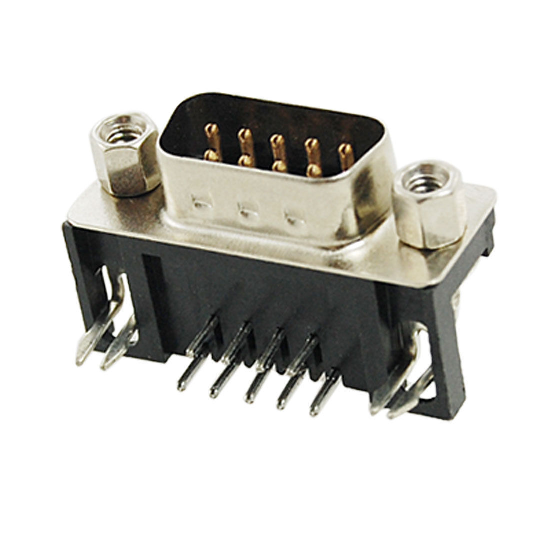 9-Pin D-SUB Male Right Angle connector 9-Pin D-SUB Male Right Angle connector |
| # | Step |
| 1. | Prepare the male header pins for all the holes of the Arduino Nano board by breaking away the required number of pins from the longer strip and shortening the longer pins to the same length as the the shorter ones. |
| 2. | Place the pins into the main board holes and place the Arduino board on top of them. |
| 3. | Holding the two boards aligned, start soldering the pins on the Arduino board |
| 4. | Keep the Arduino and the main board aligned. Solder the pins on the main board |
| 5. | Prepare two 4-pins strips of headers for logic level converter the same way as for step 1 |
| 6. | Place the pins into the main board holes and place the logic converter on top of them. Make sure the marking on the main board and the logic converter matches. Note that the logic converter board installed with components down. |
| 7. | Prepare one 4-pins and one 6-pins strip of headers for Adafruit BNO-055 board the same way as for step 1 |
| 8. | Place the pins into the main board holes and place the Adafruit BNO-055 board on top of them. |
| 9. | Keep the Adafruit BNO-055 and the main board aligned. Solder the pins on the Adafruit BNO-055 board first and then on the bottom side of the main board. |
| 10. | Remove the screw terminal from the MCP2515 CAN-Bus adapter. |
| 11. |  Cut the terminating resistor pins Cut the terminating resistor pins |
| 12. | 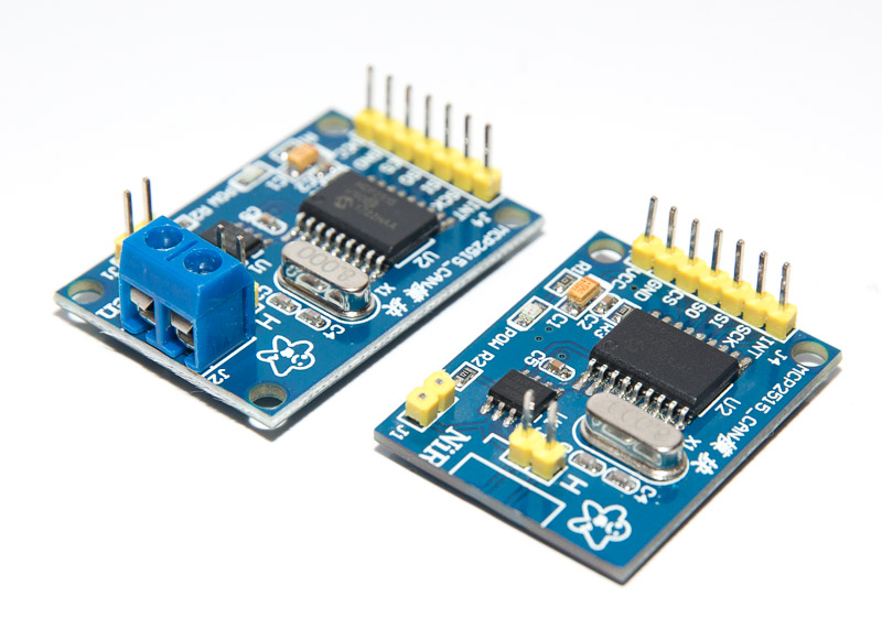 Shorten the CAN board by about 5mm from the side where screw terminal was installed Shorten the CAN board by about 5mm from the side where screw terminal was installed |
| 13. | Install and solder the CAN board to the main board. Make sure the CAN board components don’t touch the main board surface. |
| 14. | Install and solder the DB9 male connector. |
Software Download
The latest version of software (Arduino) is available at GitHub https://github.com/ExperimentalAvionics/EFIS_AHRS
New to Arduino? –
- Go to YouTube
- Search for “upload program to arduino”
- Watch a couple of videos on how to load the software into Arduino Uno. The workflow for other Arduino boards (Mega, Nano, etc) is practically identical.
Uploading the software onto the Arduino Nano board
- Click on the link for software you want to download from my GitHub. https://github.com/ExperimentalAvionics/EFIS_AHRS
- Click on the “Clone or Download” button (Green button on the right hand side)
- Click “Download ZIP”. It will initiate the file download. The file name will be something like EFIS_AHRS-master.zip
- Unzip the downloaded file into the folder where all your other Arduino projects are. On Windows it will be something like c:\Users\<MyName>\Documents\Arduino\
- The unzipped folder name will look like c:\Users\<MyName>\Documents\Arduino\EFIS_AHRS-master. You need to rename it removing the “-master“.
So the folder name will look like this: c:\Users\<MyName>\Documents\Arduino\EFIS_AHRS\ - In addition to the Arduino code the folder also contains a zip file with the 3 libraries that you need to unzip into the c:\Users\<MyName>\Documents\Arduino\libraries folder
- Start your Arduino IDE, navigate to the folder you have just created and open up the EFIS_AHRS.ino file. Note the name of the file to open is the same name as the name of the folder.
- Ensure the correct board is selected: Tools > Board > Arduino Nano
- Connect the Arduino board to your PC with a USB cable.
- Ensure the correct COM port selected: Tools > Port
- Press the “Upload” button.
- Wait for the code to be uploaded onto the Arduino board. Watch for the error messages at the bottom.
Arduino Nano Bootloader issue
There are two types of Arduino Nano boards currently available on the market. They are the same from hardware standpoint but the Bootloader is different.
You might experience some difficulties uploading the code if the version of the board is incorrectly selected. Unfortunately there is no simple and reliable way to identify the version of the Bootloader. The good news is there are only two versions of the Bootloader. 🙂
If you have a problem uploading your code simply try to change the Bootloader version in your Arduino IDE:
Tools > Processor > ATmega328P
or
Tools > Processor > ATmega328P (Old Bootloader)
Schematic PDF: EFIS_AHRS_BNO055
Schematic DipTrace: EFIS_AHRS_CAN_V21_DipTrace_Schematic
PCB Gerber: EFIS_AHRS_CAN_v2_gerber
PCB DipTrace: EFIS_AHRS_CAN_v2_DipTrace_PCB
Although the BNO055 is a self-calibrating unit, it is beneficial to calibrate it before use.
Calibration data is stored in the unit’s EEPROM and loaded every time it is powered up.
Calibration should be done with the unit fully enclosed and as close as possible to the place where it will be mounted.
Calibration requires at least one Display unit.
Calibration steps:
- Make sure the AHRS unit rests in a stable position before it powered up. It doesn’t need to be attached to the structure.
- Turn on the system and make sure gyro/magnetometer data is coming across from the AHRS unit – the system displays heading and AH.
- Push and hold encoder knob.
- Turn encoder knob to select “AHRS Cal” from the menu and press the knob. The selected line will display calibration status for the System [S], Gyro [G], Accelerometer [A] and Magnetometer [M] with “>Exit” at the end. our goal to ensure the calibration status for all AHRS components is 3. Leave it in this mode.
- Pickup the the AHRS unit and draw a figure 8 in the air until display shows M:3
- Position the AHRS unit in a stable position on all its 6 sides (if possible) for a few seconds on each side. It doesn’t matter whether or not it is parallel to the ground. It is important though for it to stay motionless in each position for a few seconds (~5 seconds). Repeat until S, G and A values are equal to 3.
- Turn the knob on the Display unit to to show “>Save” in the calibration line and push the knob to save the calibration data in the AHRS’ EEPROM
ToDo and FixIt Lists
| # | Description |
| FixIt-1 | AH drift due to circular engine vibration |
| FixIt-2 | Compass drift |
| FixIt-3 | Calibration process and local calibration data store |