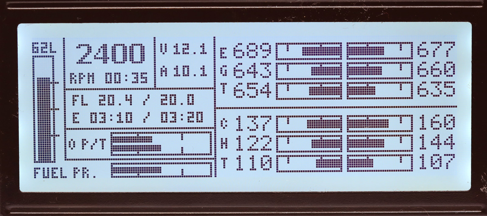
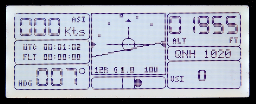
EFIS Display Unit
Updated: June 25, 2023
Status: Display Unit is operational since June 2021 with 300 hrs of flight time to date. Version 5 of the unit deployed in May 2023
EFIS Display unit ver 5 is an evolution of the previous versions of EFIS display units (see archive for details).
The main motivation factor for developing the new version of the display unit was to the display brightness adjustable in order to accommodate the requirements for Night VFR.
Physical layout of the PCB board and unit dimensions remain the same as ver 3.
IDC expansion connectors have been replaced with 15-pin D-SUB connector.
Schematic has been changed to use Arduino’s PWM ports to control brightness of the LCD display and the alarm LEDs. A few bypass capacitors have been added to improve stability of the system.
Software has also been changed to correspond to the changes in schematic. New software will work with the old version of the unit, but the brightness control function will not be available.
For on-board components please refer to Gerber/DipTrace files and schematic.
Most resistors and capacitors are SMD size 0805.
| Schematics Reference | Part Name |
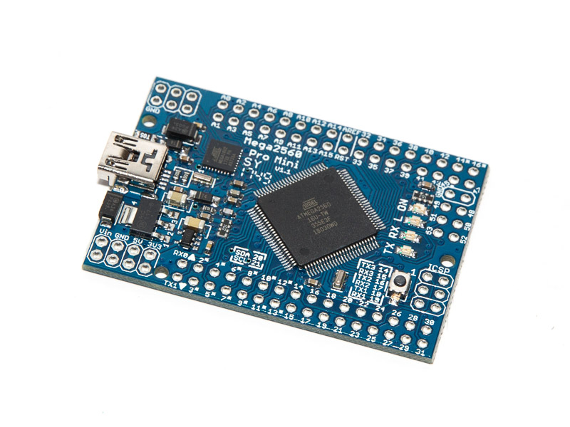 Arduino Mega 2560 Pro Mini Arduino Mega 2560 Pro Mini
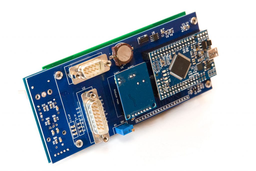
The PCB (blue) has been designed for the Arduino Mega Pro Mini (blue). See the picture on the right. Please note there is another version of Arduino Mega available on the market – Black. It will not fit the Blue PCB board | |
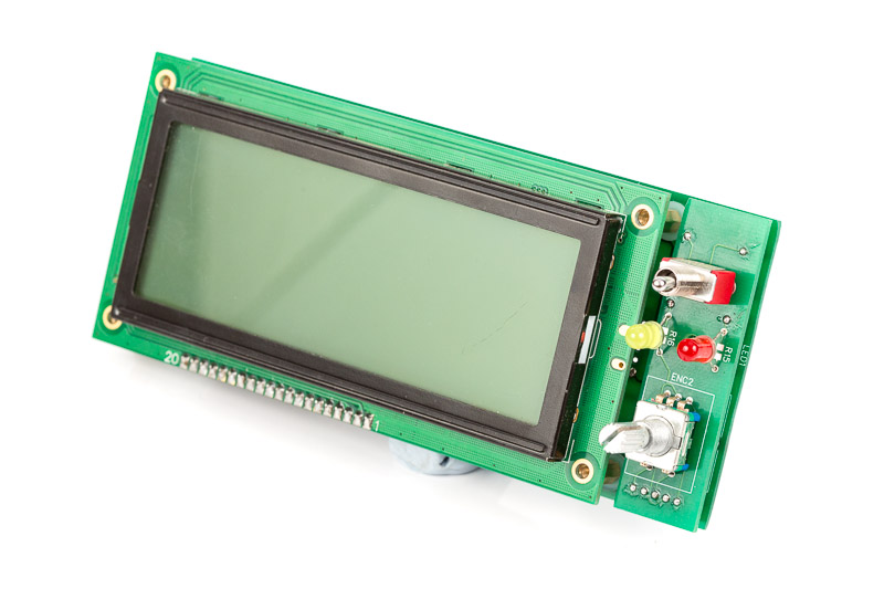
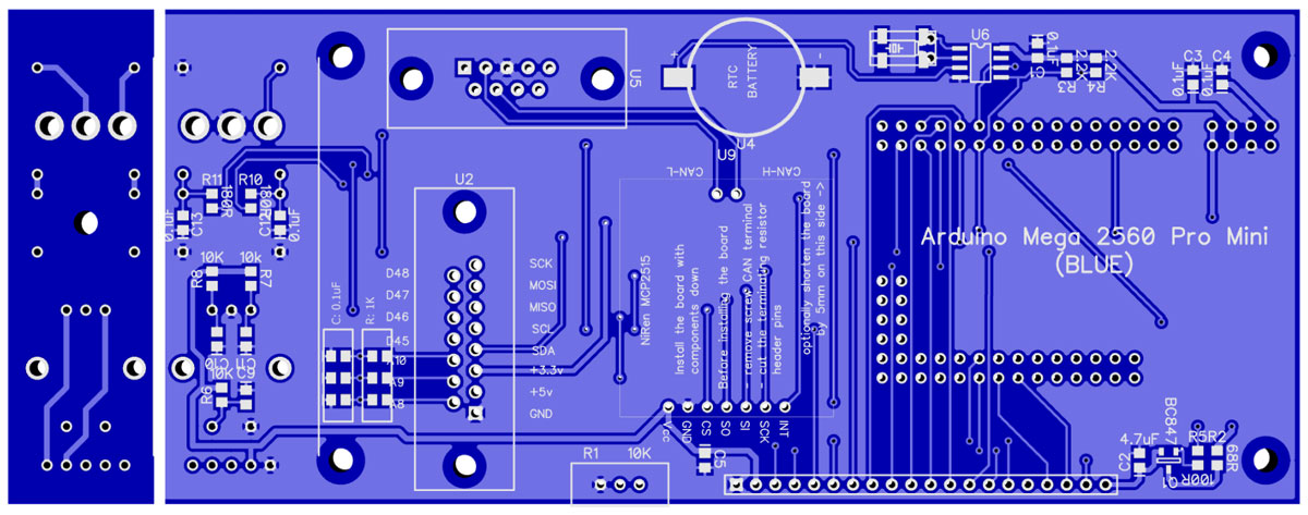 Display PCB Board (Blue) Display PCB Board (Blue) | |
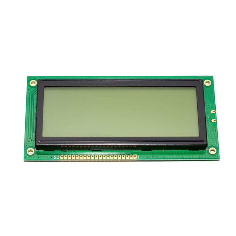 FSTN Display, 4″ 192×64 pix based on KS0107/KS0108 FSTN Display, 4″ 192×64 pix based on KS0107/KS0108
To purchase the display go to https://www.buydisplay.com/ and search for “4”192×64 Graphic LCD Display Module w/KS0107+KS0108 Black on White”. Black on White displays disappear from stock from time to time. Other colours are more frequently available. BuyDisplay also has a store on eBay. | |
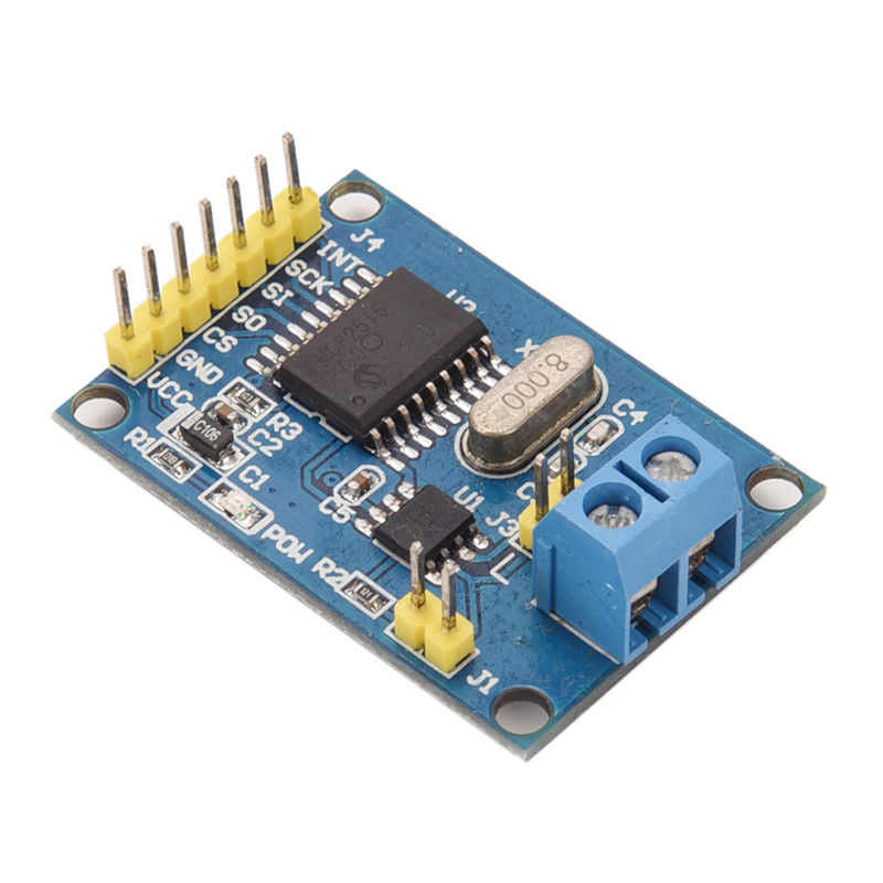 NiRen-MCP2515 CAN-Bus adapter (8Mhz) NiRen-MCP2515 CAN-Bus adapter (8Mhz)
These units are available from eBay and Aliexpress. 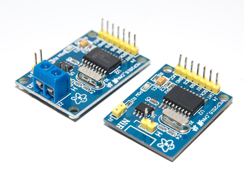 Keep in mind that you will need to de-solder the blue block connector and grind off about 5mm of the unit’ board for it to fit the final assembly. Bench grinder works well for that. | |
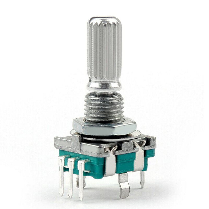 Rotary Encoder with 20mm shaft Rotary Encoder with 20mm shaft
Source: eBay, Aliexpress, Digikey, Mouser, etc | |
 10K potentiometer (trimpot) 10K potentiometer (trimpot)
Source: eBay, Aliexpress, Digikey, Mouser, etc | |
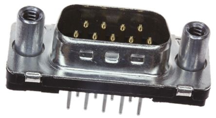 9-Pin D-SUB Male Straight connector 9-Pin D-SUB Male Straight connector
Source: eBay, Aliexpress, Digikey, Mouser, etc | |
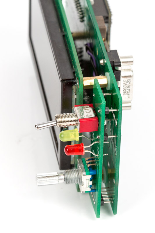
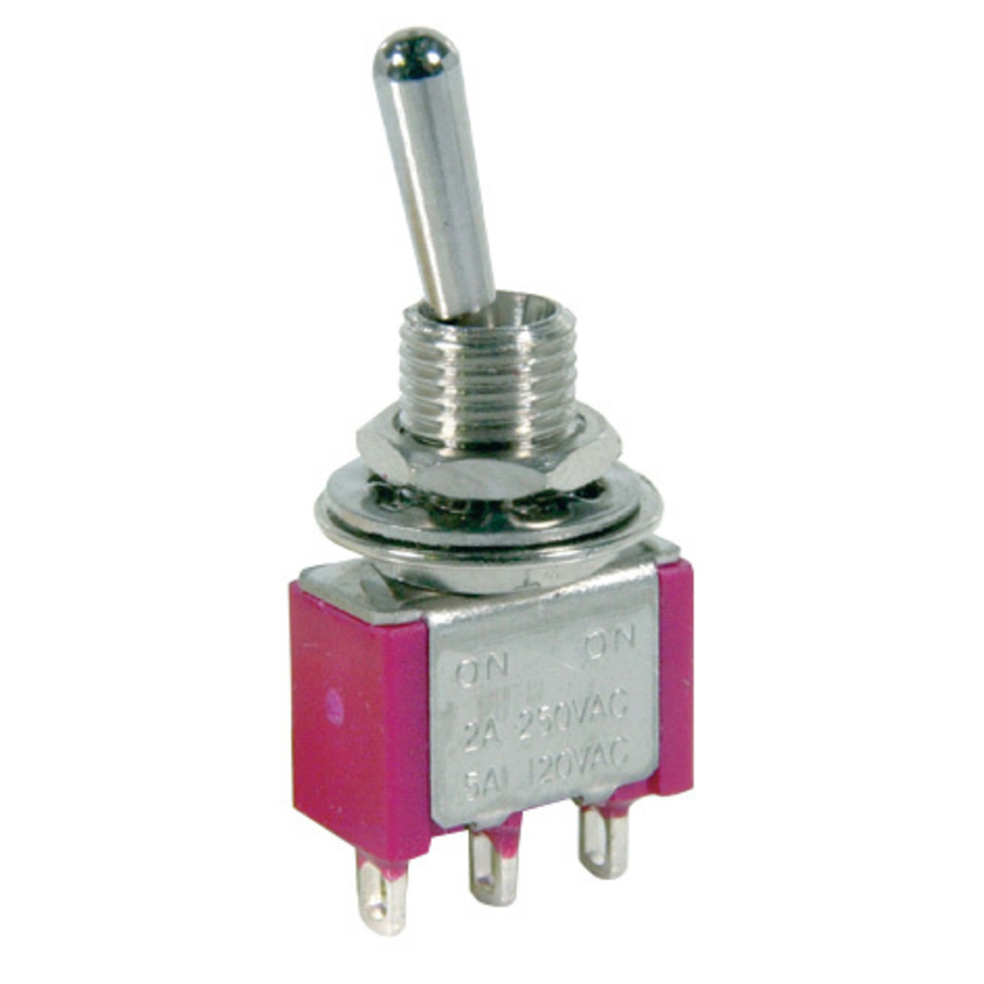 Toggle switch (optional) Toggle switch (optional)
Source: eBay, Aliexpress, Digikey, Mouser, etc | |
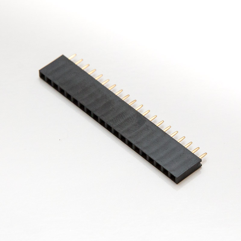 20-pin female header 20-pin female header
Source: eBay, Aliexpress | |
 Five (5) 40-pin Male Header terminal strips. Five (5) 40-pin Male Header terminal strips.
Source: eBay, Aliexpress | |
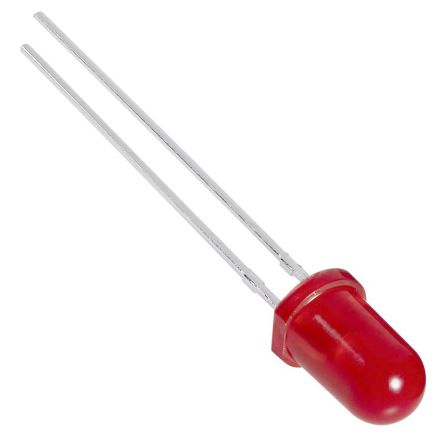 2 trough-hole LEDs and 2 appropriate SMD 0805 resistors (optional) 2 trough-hole LEDs and 2 appropriate SMD 0805 resistors (optional) | |
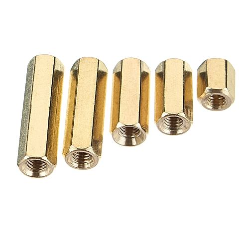 Four 11mm standoffs with M3 treads, copper (cheap) or alluminium (lighter and look nicer) Four 11mm standoffs with M3 treads, copper (cheap) or alluminium (lighter and look nicer)
Source: eBay, Aliexpress. | |
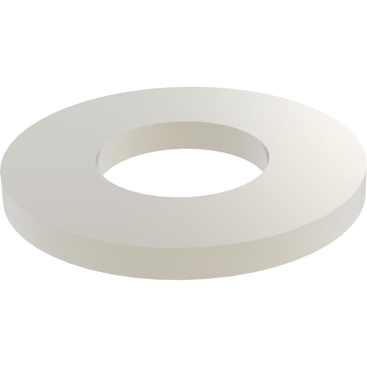 20 Nylon washers 1mm thick 20 Nylon washers 1mm thick
Source: eBay, Aliexpress, Digikey | |
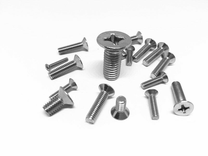 Four M3 bolts 12mm countersunk head Four M3 bolts 12mm countersunk head | |
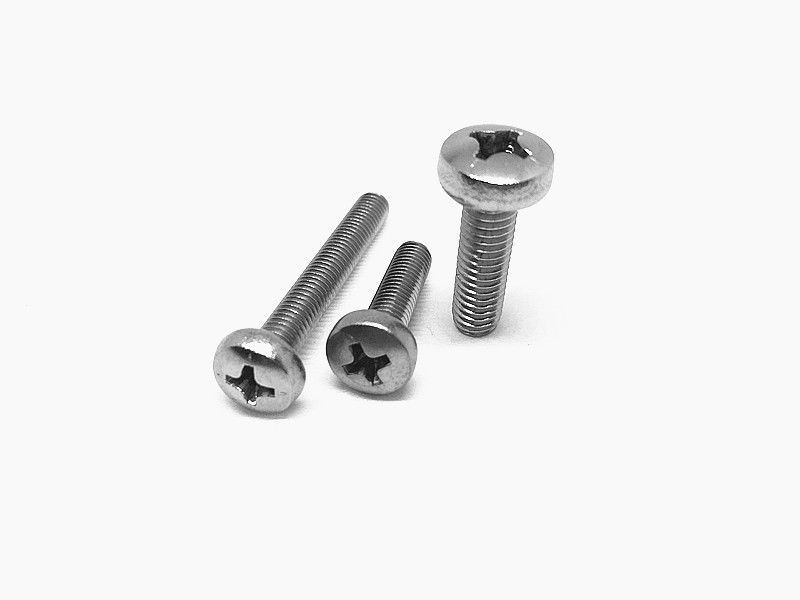 Four M3 bolts 6mm button head Four M3 bolts 6mm button head |
Instructions for PCB ver 5 are coming soon
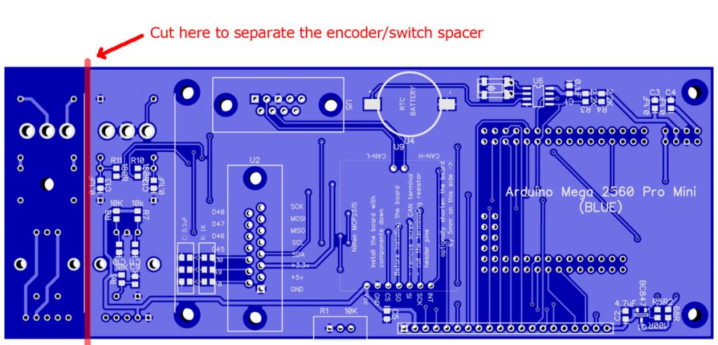
If you have made the PCB board using the DipTrace or Gerber files from this site or purchased a bare PCB board from our store you will need to separate the encoder spacer from the rest of the board.
The latest version of software (Arduino) is available at GitHub https://github.com/ExperimentalAvionics/Avionics_Display_19264
Make sure to set CYL variable according to the number cylinders of your engine. (Line 17 in the Avionics_Display_19264.ino)
Currently supported values are 6 – for the 6-cylinder sensor board and 4 – for the 4 cylinder sensor board.
New to Arduino? –
- Go to YouTube
- Search for “upload program to arduino”
- Watch a couple of videos on how to load the software into Arduino Uno. The workflow for other Arduino boards (Mega, Nano, etc) is practically identical.
Uploading the software onto the Arduino Mega board
- Click on the link for software you want to download from my GitHub. https://github.com/ExperimentalAvionics/Avionics_Display_19264
- Click on the “Clone or Download” button (Green button on the right hand side)
- Click “Download ZIP”. It will initiate the file download. The file name will be something like Avionics_Display_19264-master.zip
- Unzip the downloaded file into the folder where all your other Arduino projects are. On Windows it will be something like c:\Users\<MyName>\Documents\Arduino\
- The unzipped folder name will look like c:\Users\<MyName>\Documents\Arduino\Avionics_Display_19264-master. You need to rename it removing the “-master“.
So the folder name will look like this: c:\Users\<MyName>\Documents\Arduino\Avionics_Display_19264\ - In addition to the Arduino code the folder also contains a zip file with the 3 libraries that you need to unzip into the c:\Users\<MyName>\Documents\Arduino\libraries folder
- Start your Arduino IDE, navigate to the folder you have just created and open up the Avionics_Display_19264.ino file. Note the name of the file to open is the same name as the name of the folder.
- Ensure the correct board is selected: Tools > Board > Arduino Mega or Mega 2560
- Connect the Arduino board to your PC with a USB cable.
- Ensure the correct COM port selected: Tools > Port
- Press the “Upload” button.
- Wait for the code to be uploaded onto the Arduino board. Watch for the error messages at the bottom.
Schematic PDF: EFIS_Display_Schematic_v50
Schematic DipTrace (.zip): Schematic_EFIS19264_Display_V5
PCB DipTrace file (.zip): EFIS_v50_Blue
PCB Gerber file (.zip): EFIS_v50R1_Blue_gerber
ToDo and FixIt Lists
| # | Description |
| ToDo-1 | Add a functionality to control AHRS calibration from the Display Unit |
| ToDo-2 | Add optional European and US units for speed, altitude and pressure. (km/h, mph, meters, mmHg, inHg) |
| ToDo-3 | Clock sync with GPS |