CAN-Bus
Updated: December 14, 2023
 This page contains the information about implementation of CAN for interconnecting Experimental Avionics devices.
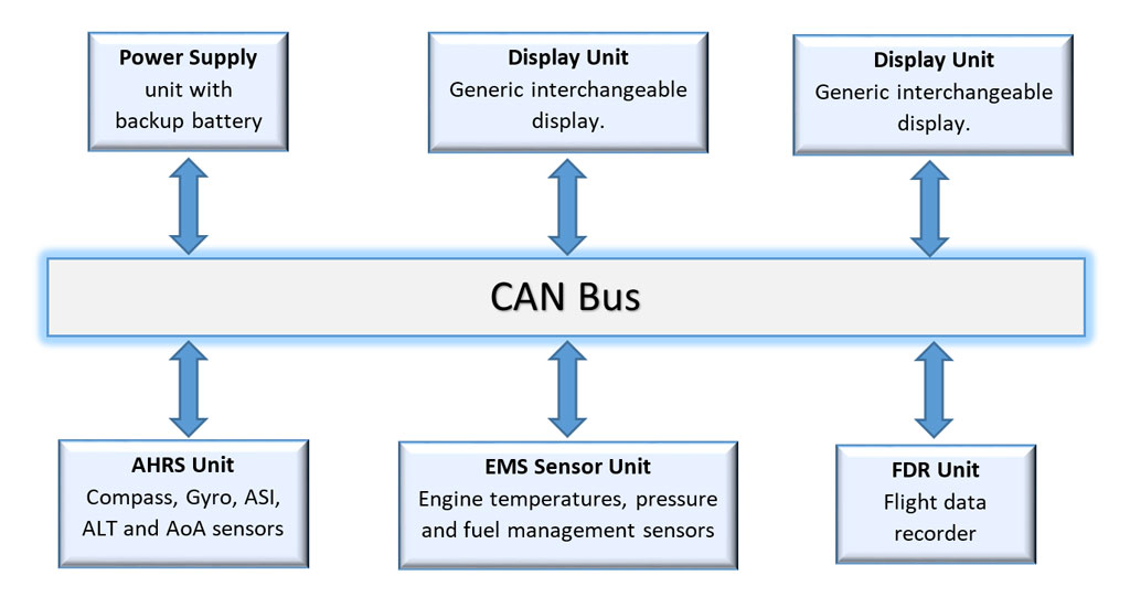
Interconnecting all the avionics through CAN opens up a lot of opportunities to create very flexible and open architecture.
CAN is very reliable and relatively simple network protocol for connecting devices via a pair of twisted wires developed by Bosch in 1980s..
CAN has become an industry standard in automotive and aviation for communication between devices and controllers.
If it is good for Toyota and Airbus, then it is good enough for me. Avionics leaders such as Dynon, Garmin, NGT ect also use some form of CAN to interconnect their devices.
Here is a good short article about CAN and aviation: http://www.aviationtoday.com/2009/05/01/can-bus-in-aviation/
General notes
CAN is used to deliver information from various sensors (EMS, AHRS, Module-A) to display units.
Hardware implementation of CAN is based on NiRen breakout board built on MCP2515 chip.
Selected network speed – 500 Kbit/sec.
While all the Arduino-based units worked on 1 Mbit/sec OK, the Raspberry Pi based unit didn’t want to work on that speed with the NiRen MCP2515 board. So I lowered the speed to 500 Kbit/sec for all units. The speed is still sufficient for adequate performance of the system.
Terminating resistors are available on the breakout boards. Two devices connected at the ends of the bus should have the terminating resistors enabled by shorting (connecting together) the relevant pins on the MCP2515 board.
Cables and Connectors
CAN-Bus uses twisted pair cables to combat interference from other circuits.
Normally a CAN-Bus cable consists of 4 wires – one twisted pair for CAN itself and the other for delivering power to the unit (sensor board). It is OK to use cheap ribbon cables for short (< 0.3m/1′) runs.
For workbench testing any cheap wire will work just fine. Stranded computer network wire is a good option.
For installation on the aircraft use Tefzel cable 22 or 20 AWG.
9-pin D-Sub female connectors are normally used for making a CAN cable.
Soldered connectors are cheap and widely available, however they might not be suitable for the environments exposed to vibrations. When using the soldered connectors for installation on the aircraft a special care should be taken to properly secure the wires inside the back-shell to avoid fatigue cracks on the edge of the solder joint.
Crimped connectors might be a better option, although they are a bit expensive.
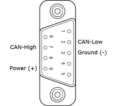 CAN-Bus connector pin-out:
Pin 2: CAN-Low
Pin 3: Ground (-)
Pin 7: CAN-High
Pin 9: Power (+)
CAN Messages Overview
Messages sent “blind” (broadcasted).
In other words sensor sends messages on regular intervals and doesn’t care whether anyone asked for it.
In some cases devices can “request” the information and expect a “response”. The response will be sent with high priority message ID and the requesting device waits for the “response” ignoring other messages. This is done only for configuration tasks such as time sync etc. This type of data exchange should not be performed in-flight.
All messages use standard 11 bit ID.
All messages are standard length – between 1 and 8 bytes.
Each message contains 1 or more pieces of information. For example engine temperature information EGT and CHT for cylinder 1 and 2 will come in one 8 byte message – 2 bytes for each temperature.
CAN Masks
Each display unit listens to the information relevant to it. So, EFIS ignores engine data, EMS Display ignores flight information data. Some data can be addressed to both display units. Main purpose of this arrangement is to increase display’s information throughput. So, CAN adapters on the display units have the following filter masks:
EFIS CAN mask: 0000 1000
EMS CAN mask: 0001 0000
In other words if the sensor is sending a message to EMS Display, the message id (CAN ID) should have the fifth bit set to 1. See the Message ID allocation chart below for more details.
CAN IDs and message structure
| ID | Bytes | ||||||||||
| Message description | BIN | DEC | HEX | 1 | 2 | 3 | 4 | 5 | 6 | 7 | 8 |
| EMS. RPM, Fuel Flow, Fuel Pressure | 00 0011 0010 | 050 | 032 | RPM | F. Press[Bars x 1000] | F. Flow[L/h x 100] | |||||
| EMS. Fuel Level 1, Fuel Level 2 | 00 0101 0000 | 080 | 050 | Fuel Lvl1 | Fuel Lvl2 | ||||||
| EMS. Oil Temp. Oil Pres | 00 0101 0001 | 081 | 051 | Oil Pressure[Bars x 1000 (kPa x 10)] | Oil Temp[°C] x 10 | ||||||
| EMS. EGT 1,2, CHT 1,2 | 00 0101 0010 | 082 | 052 | EGT1 | EGT2 | CHT1 | CHT2 | ||||
| EMS. EGT 3,4, CHT 3,4 | 00 0101 0011 | 083 | 053 | EGT3 | EGT4 | CHT3 | CHT4 | ||||
| EMS. EGT 5,6, CHT 5,6 | 00 0101 0100 | 084 | 054 | EGT5 | EGT6 | CHT5 | CHT6 | ||||
| EMS. Volts and Amps | 00 0101 0101 | 085 | 055 | Main Electric Bus Voltage[unsigned millivolts] | Alternator Amps[unsigned milliamps] | Battery Amps[signed milliamps] | |||||
| Module-A. Backup Battery voltage and charger status | 00 0101 0110 | 086 | 056 | Backup Battery Voltage[unsigned millivolts] | Status:b00000001 – CHGOKb00000010 – ACOK
See MP26123 datasheet for details on its meaning |
Battery temperatureSigned deg C | |||||
| EMS. Engine Time | 00 0111 0000 | 112 | 070 | Engine Time (Tacho) | Engine Time (Clock) | ||||||
| . | |||||||||||
| Flight Time (Airswitch) | 00 0111 0000 | 120 | 078 | Airswitch | |||||||
| . | |||||||||||
| Time sync broadcast | 00 0001 1001 | 025 | 019 | YY | MM | DD | HH | MI | SS | ||
| Airspeed, Altitude, VSI | 00 0010 1000 | 040 | 028 | Airspeed (knots) | Altitude (ft) | Vert. Speed (ft/min) | |||||
| AoA | 00 0010 1000 | 041 | 029 | AoA | |||||||
| Outside Temperature and Humidity. | 00 0010 1010 | 042 | 02A | OAT C x 10 | Humidity % | ||||||
| Raw Altimeter data. | 00 0010 1011 | 043 | 02B | Static Pressure (hPa) x 10 | Sensor Temp | ||||||
| QNH (hPa) | 00 0010 1110 | 046 | 02E | QNH | |||||||
| . | |||||||||||
| AHRS. Orientation | 00 0100 1000 | 072 | 048 | Heading | Pitch | Roll | Turn Rate | ||||
| AHRS. Acceleration: X, Y, Z | 00 0100 1001 | 073 | 049 | AccX | AccY | AccZ | Calib. | ||||
| AHRS Control Commands | 00 0010 0011 | 35 | 023 | Calibration 1 = Save |
|||||||
| . | |||||||||||
| GPS: Coordinates (Deg*1000000) | 00 0110 0011 | 099 | 063 | Latitude | Longitude | ||||||
| GPS: GS, Alt, Track True and Magnetic | 00 0110 0100 | 100 | 064 | Ground Sp. | Alt | TRK-True | TRK-Mag | ||||
| GPS Satellite signal level | 00 0110 0101 | 101 | 65 | Number of satellites available | Sigbal level for sat 1 and 2 | Sigbal level for sat 3 and 4 | Sigbal level for sat 5 and 6 | Sigbal level for sat 7 and 8 | Sigbal level for sat 9 and 10 | Sigbal level for sat 11 and 12 | Sigbal level for sat 13 and 14 |
| GLONASS Satellite signal Level | 00 0110 0110 | 102 | 66 | Number of satellites available | Sigbal level for sat 1 and 2 | Sigbal level for sat 3 and 4 | Sigbal level for sat 5 and 6 | Sigbal level for sat 7 and 8 | Sigbal level for sat 9 and 10 | Sigbal level for sat 11 and 12 | Sigbal level for sat 13 and 14 |
Message ID allocation chart
| Priority 1 | Priority 2 | Priority 3 | Priority 4 | |||||
| OTHER | 00 0000 0000 | 000 | 00 0010 0000 | 032 | 00 0100 0000 | 064 | 00 0110 0000 | 096 |
| 00 0000 0001 | 001 | 00 0010 0001 | 033 | 00 0100 0001 | 065 | 00 0110 0001 | 097 | |
| 00 0000 0010 | 002 | 00 0010 0010 | 034 | 00 0100 0010 | 066 | 00 0110 0010 | 098 | |
| 00 0000 0011 | 003 | 00 0010 0011 | 035 | 00 0100 0011 | 067 | 00 0110 0011 | 099 | |
| 00 0000 0100 | 004 | 00 0010 0100 | 036 | 00 0100 0100 | 068 | 00 0110 0100 | 100 | |
| 00 0000 0101 | 005 | 00 0010 0101 | 037 | 00 0100 0101 | 069 | 00 0110 0101 | 101 | |
| 00 0000 0110 | 006 | 00 0010 0110 | 038 | 00 0100 0110 | 070 | 00 0110 0110 | 102 | |
| 00 0000 0111 | 007 | 00 0010 0111 | 039 | 00 0100 0111 | 071 | 00 0110 0111 | 103 | |
| EFIS | 00 0000 1000 | 008 | 00 0010 1000 | 040 | 00 0100 1000 | 072 | 00 0110 1000 | 104 |
| 00 0000 1001 | 009 | 00 0010 1001 | 041 | 00 0100 1001 | 073 | 00 0110 1001 | 105 | |
| 00 0000 1010 | 010 | 00 0010 1010 | 042 | 00 0100 1010 | 074 | 00 0110 1010 | 106 | |
| 00 0000 1011 | 011 | 00 0010 1011 | 043 | 00 0100 1011 | 075 | 00 0110 1011 | 107 | |
| 00 0000 1100 | 012 | 00 0010 1100 | 044 | 00 0100 1100 | 076 | 00 0110 1100 | 108 | |
| 00 0000 1101 | 013 | 00 0010 1101 | 045 | 00 0100 1101 | 077 | 00 0110 1101 | 109 | |
| 00 0000 1110 | 014 | 00 0010 1110 | 046 | 00 0100 1110 | 078 | 00 0110 1110 | 110 | |
| 00 0000 1111 | 015 | 00 0010 1111 | 047 | 00 0100 1111 | 079 | 00 0110 1111 | 111 | |
| EMS | 00 0001 0000 | 016 | 00 0011 0000 | 048 | 00 0101 0000 | 080 | 00 0111 0000 | 112 |
| 00 0001 0001 | 017 | 00 0011 0001 | 049 | 00 0101 0001 | 081 | 00 0111 0001 | 113 | |
| 00 0001 0010 | 018 | 00 0011 0010 | 050 | 00 0101 0010 | 082 | 00 0111 0010 | 114 | |
| 00 0001 0011 | 019 | 00 0011 0011 | 051 | 00 0101 0011 | 083 | 00 0111 0011 | 115 | |
| 00 0001 0100 | 020 | 00 0011 0100 | 052 | 00 0101 0100 | 084 | 00 0111 0100 | 116 | |
| 00 0001 0101 | 021 | 00 0011 0101 | 053 | 00 0101 0101 | 085 | 00 0111 0101 | 117 | |
| 00 0001 0110 | 022 | 00 0011 0110 | 054 | 00 0101 0110 | 086 | 00 0111 0110 | 118 | |
| 00 0001 0111 | 023 | 00 0011 0111 | 055 | 00 0101 0111 | 087 | 00 0111 0111 | 119 | |
| BOTH | 00 0001 1000 | 024 | 00 0011 1000 | 056 | 00 0101 1000 | 088 | 00 0111 1000 | 120 |
| 00 0001 1001 | 025 | 00 0011 1001 | 057 | 00 0101 1001 | 089 | 00 0111 1001 | 121 | |
| 00 0001 1010 | 026 | 00 0011 1010 | 058 | 00 0101 1010 | 090 | 00 0111 1010 | 122 | |
| 00 0001 1011 | 027 | 00 0011 1011 | 059 | 00 0101 1011 | 091 | 00 0111 1011 | 123 | |
| 00 0001 1100 | 028 | 00 0011 1100 | 060 | 00 0101 1100 | 092 | 00 0111 1100 | 124 | |
| 00 0001 1101 | 029 | 00 0011 1101 | 061 | 00 0101 1101 | 093 | 00 0111 1101 | 125 | |
| 00 0001 1110 | 030 | 00 0011 1110 | 062 | 00 0101 1110 | 094 | 00 0111 1110 | 126 | |
| 00 0001 1111 | 031 | 00 0011 1111 | 063 | 00 0101 1111 | 095 | 00 0111 1111 | 127 | |