EFIS Module-A
Updated: June 29, 2023
Status: Operational with over 300 flight hours in service
Module A is the Air-pressure module for EFIS. It provides Altitude, Airspeed, Angle of Attack (AoA) and Outside Air Temperature (OAT) information to other systems via CAN-Bus network. With introduction of backup power controller into CAN HUB, Module-A also provide information about backup battery status.
The unit designed as an open platform with configurable optional analog and digital inputs. See Extensions connections for details.
The module has its own processor (Arduino Nano) and it is powered from CAN-Bus (CAN-HUB)
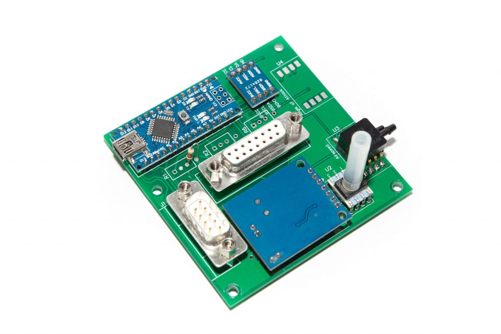


Differential pressure sensors should be selected according to the aircraft speed range MPXV5010DP is good up to 240 knots.
Most of the testing has been done with airspeed sensor being MPXV5010DP and angle of attack (AoA) sensor being MPXV7002DP.
Although using MPXV5010DP for AoA sensor gave acceptable results, the MPXV7002DP provided better sensitivity.
As of mid 2023 the Angle of Attack functionality has not been flight tested due to other priorities.
Extensions connections
Module-A has a 15-pin female D-SUB connector for additional sensors such as Outside Air Temperature (OAT), Backup Battery status, flaps position (not yet implemented).
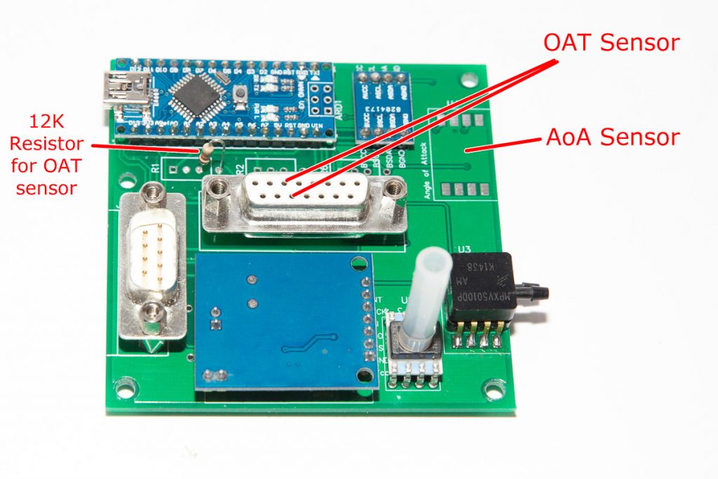
Outside Air Temperature sensor
OAT information is required for True Airspeed calculation. It is also important to avoid icing conditions.
Dynon two-wire OAT sensor (NTC thermistor) connected to pin 6 and 13 (ground). Any thermistor can be used here. Just adjust Steinhart–Hart coefficients in the code. If the coefficients are not available from manufacturer, they can be easily determined using this calculator: https://rusefi.com/Steinhart-Hart.html
Backup Battery Status
CAN HUB ver 3 and later provides backup power capability required for Night VFR. Module-A provides an interface between battery charge controller and CAN-Bus.
Backup Battery Voltage sensor connected to pin 5 of 15-pin female D-SUB connector.
Voltage measured by Arduino port A6 via voltage divider 2.2M + 680K. It provides max measured voltage of 21V.
SMD resistors placed at bottom side of the PCB on the pads for R2 trimpot.
Through-hole resistors can be used instead.
Installing trimpot is too risky and unnecessarily complex.
Resistor R3 (Low pass filter) is replaced with shunt (zero Ohm resistor).
Keep the capacitor C9.
NTC battery temperature sensor connected to pin 4 of 15-pin female D-SUB connector.
Voltage measured by Arduino’s port A7
Temperature sensor consists of voltage divider of a constant 10K resistor (located on CAN HUB board) and a 10K thermistor with
negative temperature coefficient (NTC).
Its output used by the charger chip as well.
Reference voltage (3.3v) supplied by the charge chip on CAN HUB board.
The input voltage on port A7 will be way below 3.3v so there is no need for additional voltage divider on Module-A side.
So, the non-ground pads of the R6 trip pot position should be connected. Use 0R SMD resistor or small piece of wire.
Charge OK signal (CHGOK) connected directly to D7 via pin 7 of 15-pin DSUB connector,
Power OK (ACOK) connected directly to D9 via pin 8 of DSUB connector.
Parts List
| Schematics Reference | Part Name |
| ARD |  Arduino Nano Arduino Nano
Source: Aliexpress, eBay, etc Some Nano’s come with the old bootloader. Not a problem. Just be aware of that and select appropriate setting when uploading the software, |
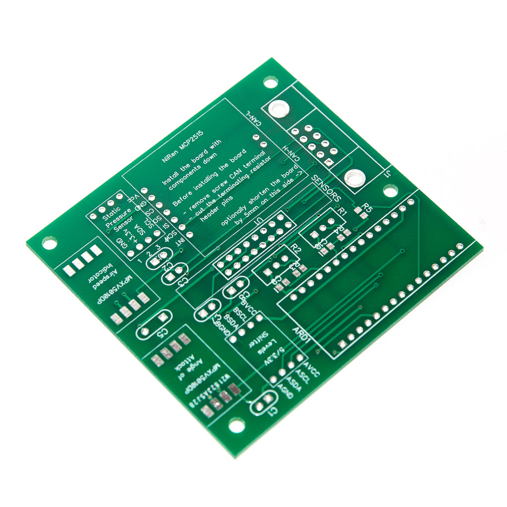 Module-A PCB Board Module-A PCB Board
Available in our store as partially assembled (SMD resistors and caps on it) or bare board. | |
| MCP2512 | 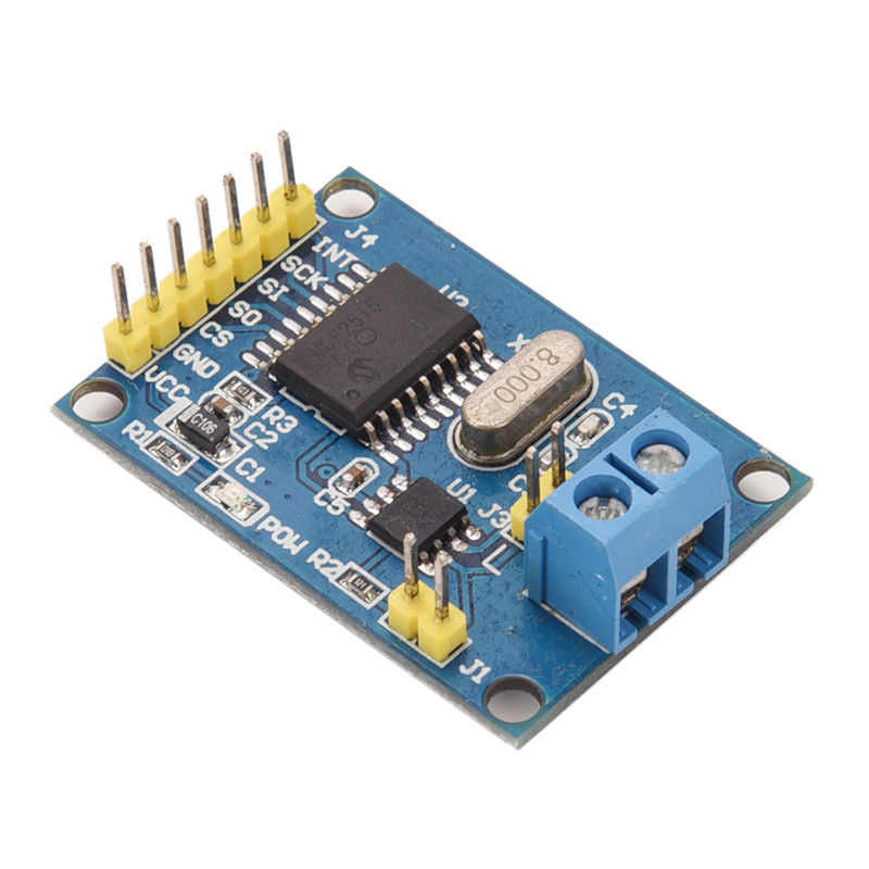 NiRen-MCP2515 CAN-Bus adapter (8Mhz) NiRen-MCP2515 CAN-Bus adapter (8Mhz)
Source: Aliexpress, eBay, etc Note: You will need to remove the block connector and shorten (grind off) the board by about 5mm (~3/16″) |
| U2 |  Honeywell HSCDANN015PA2A3 Static Pressure Sensor Honeywell HSCDANN015PA2A3 Static Pressure Sensor
Source: Mouser, DigiKey, RSonline, Element14, etc There a few models with similar pressure range. Please note that if you choose different model its I2C address could be different, so relevant change in the code would be required. |
| AIRSPEED |  Airspeed differential pressure sensor MPXV5010DP Airspeed differential pressure sensor MPXV5010DP
Other similar model can be used instead. Some minor code change might be required though.
|
| AOA | AoA differential pressure sensor MPXV7002DP, only needed if you want AoA information displayed.
Other similar model can be used instead. Some minor code change might be required though.
|
| J1 | 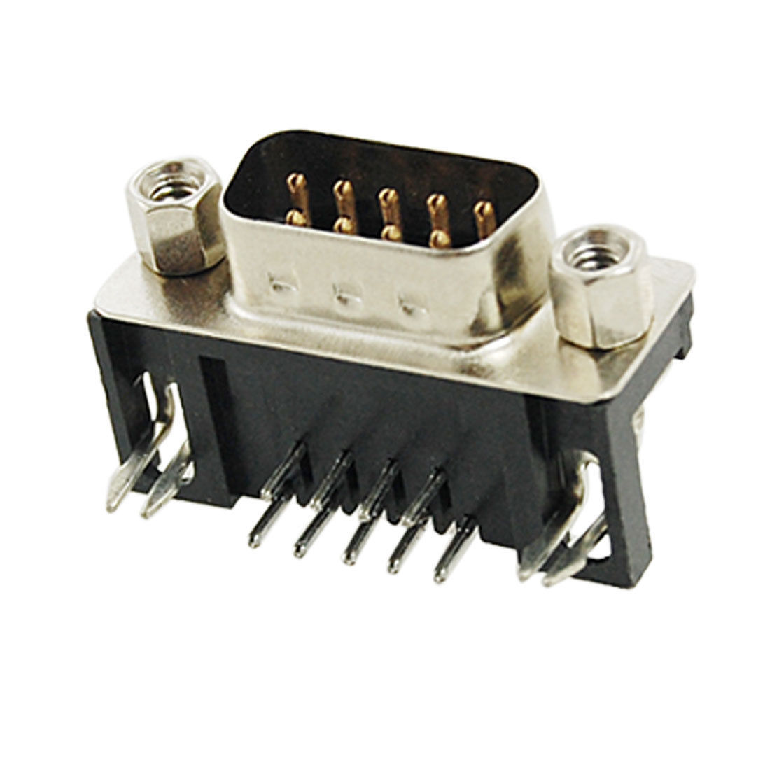 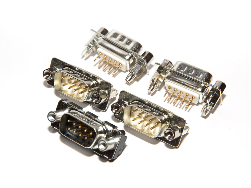 9-Pin D-SUB Male connector 9-Pin D-SUB Male connector
Straight or Right Angle depending on the installation of the board in avionics compartment. I found Straight coonector is better in most cases |
| U2 | 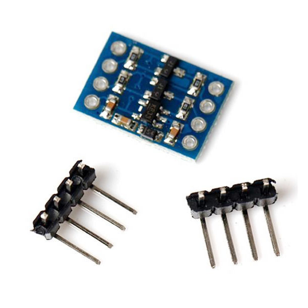 5v – 3v Logic Converter I2C. (Level Shifter) 5v – 3v Logic Converter I2C. (Level Shifter)
|
| To be continued…. | |
Assembly Instructions
| # | Step |
| 1. | Prepare the male header pins for all the holes of the Arduino Nano board by breaking away the required number of pins from the longer strip and shortening the longer pins to the same length as the the shorter ones. |
| 2. | Place the pins into the main board holes and place the Arduino board on top of them. |
| 3. | Holding the two boards aligned, start soldering the pins on the Arduino board |
| 4. | Keep the Arduino and the main board aligned. Solder the pins on the main board |
| 5. | Prepare two 4-pins strips of headers for logic level converter the same way as for step 1 |
| 6. | Place the pins into the main board holes and place the logic converter on top of them. Make sure the marking on the main board and the logic converter matches. Note that the logic converter board installed with its components down. |
| 7. | 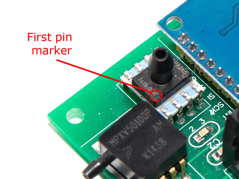 Install and solder the Honeywell static pressure sensor. Make sure the sensor is installed right way around. Install and solder the Honeywell static pressure sensor. Make sure the sensor is installed right way around. |
| 8. | Remove the screw terminal from the MCP2515 CAN-Bus adapter. |
| 9. |  Cut the terminating resistor pins Cut the terminating resistor pins |
| 10. | 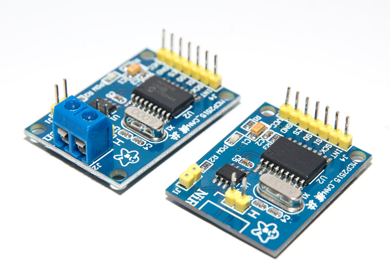 Shorten the CAN board by about 5mm (~3/16″) from the side where screw terminal was installed Shorten the CAN board by about 5mm (~3/16″) from the side where screw terminal was installed |
| 11. | Install and solder the CAN board to the main board. Make sure the CAN board components don’t touch the main board surface. |
| 12. | Install and solder the DB9 male connector. |
| 13. | Install and solder DB15 connector. |
| To be continued…. | |
Software Download
The latest version of software (Arduino) is available at GitHub https://github.com/ExperimentalAvionics/EFIS_ModuleA
New to GitHub? – Here is a quick GitHub guide.
New to Arduino? –
- Go to YouTube
- Search for “upload program to arduino”
- Watch a couple of videos on how to load the software into Arduino Uno.
The workflow for other Arduino boards (Mega, Nano, etc) is practically identical.
Arduino Nano Bootloader issue
There are two types of Arduino Nano boards currently available on the market. They are the same from hardware standpoint but the Bootloader is different.
You might experience some difficulties uploading the code if the version of the board is incorrectly selected. Unfortunately there is no simple and reliable way to identify the version of the Bootloader.
If you have a problem uploading your code simply try to change the Bootloader version in your Arduino IDE:
Tools > Processor > ATmega328P
or
Tools > Processor > ATmega328P (Old Bootloader)
Schematics and PCBs
EFIS Module-A ver. 3.1 Schematics (PDF): Module-A_Schematic
EFIS Module-A ver. 3.1 Schematics DipTrace (.zip): EFIS_Module_A_ver31_Schematic_DipTrace
EFIS Module-A ver. 3.1 PCB Gerber (.zip): EFIS_Module_A_PCB_v31_gerber
EFIS Module-A ver. 3.1 PCB DipTrace (.zip): EFIS_Module_A_PCB_v31_DipTrace
ToDo/FixIt
| # | Description |
| Add i2c interface for AoA | |
| Add rs232 interface for transponder altitude encoder | |
| Add static pressure sensor’s temperature into Can messages as well as the serial messages for transponder encoder. | |