Flight Data Recorder
Data Logger, ADS-B, Glass Panel and Aural Warning System
Updated: July 20, 2023
Flight Data Recorder (FDR) module is a multifunctional unit based on Raspberry Pi.
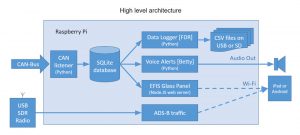
Its main functions are:
- Flight data recorder
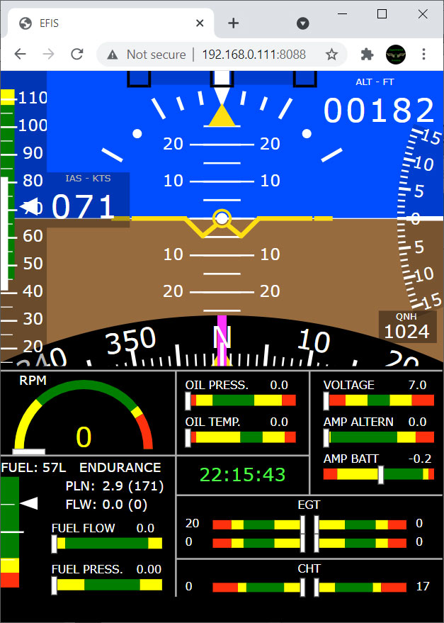
The unit records all flight and engine parameters on SD card in CSV format. - Tablet-based “Glass Panel”.
All flight and engine information can be displayed on any Android or iOS tablet similar to Garmin or Dynon EFIS displays. See Glass Panel section for detailed software configuration instructions. - ADS-B In traffic information receiver.
The unit receives and processes ADS-B traffic information and feeds the data to your favorite Electronic Flight Bag software (for example OzRunways) - GPS
The unit processes GPS data and feeds it into CAN Bus for other units to use. - Aural notifications
Unit detects abnormal and dangerous situations and provide audio (voice) warnings via intercom.
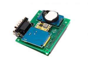
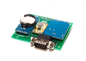
The unit consists of a Raspberry Pi single board computer and the interface board (aka Hat).
Just like all other units in this ecosystem the interface board uses RiNen MCP2515 CAN adapter for communication with other units. It also has its own time keeping device (RTC) to ensure accurate logging of the flight data in the flight recorder..
The FDR setup is suitable for automotive applications too. It is compatible with OBD-II as far as CAN-Bus compatibility goes and can be used with most RPi based OBD-II data logger software available as Open Source.

Parts list:
| Schematics Reference | Part Name |
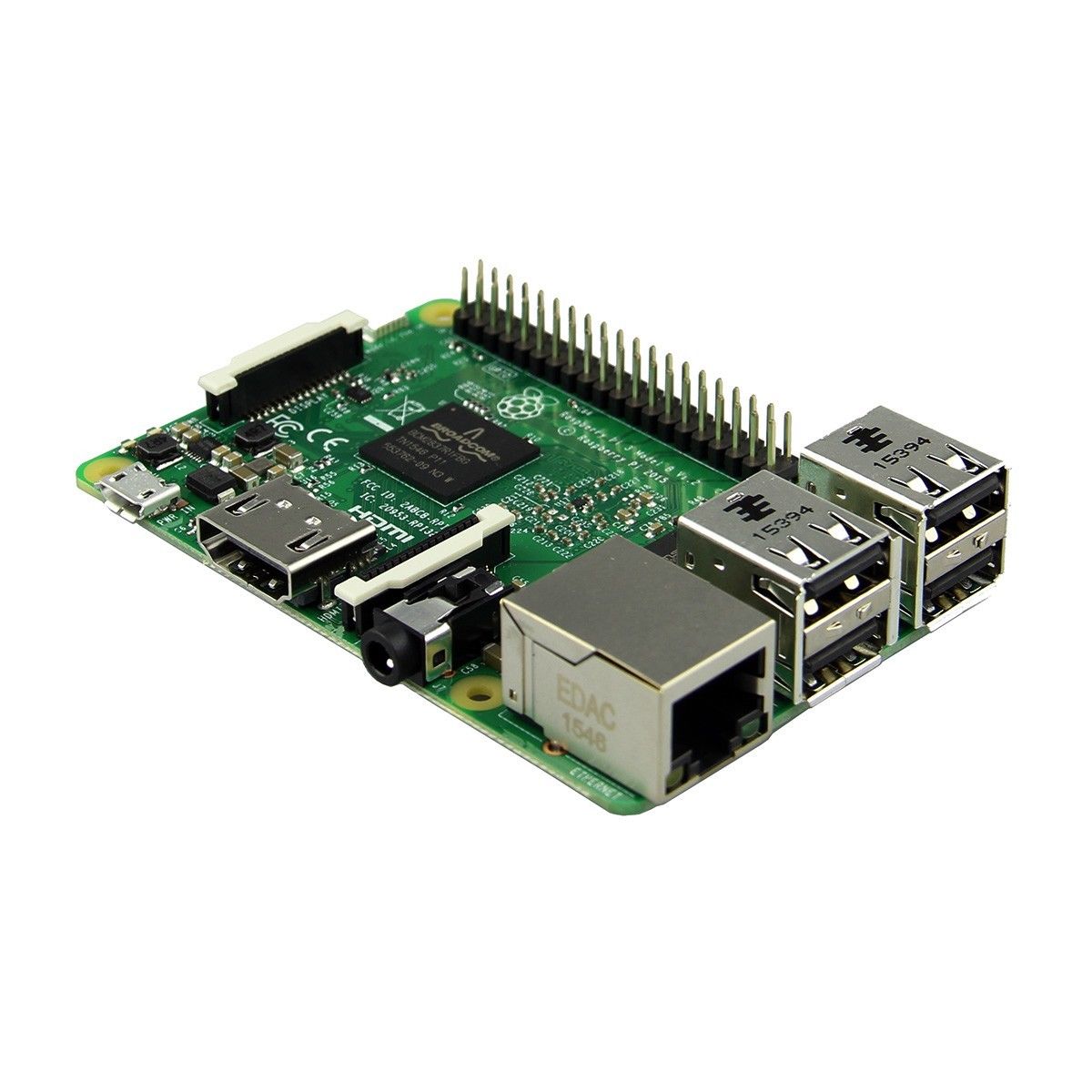 Raspberry Pi 3 Model B or B+ Raspberry Pi 3 Model B or B+ | |
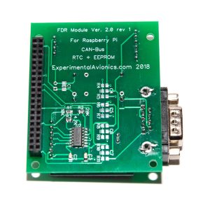
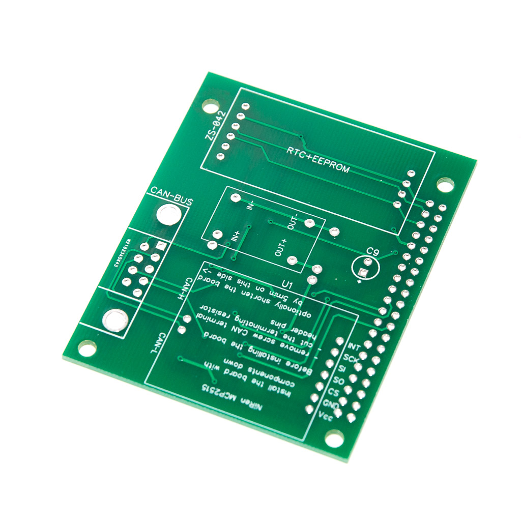 FDR (Data Logger) PCB Board (Available in our Store)The PCB board comes with all the SMD components soldered on the boards . FDR (Data Logger) PCB Board (Available in our Store)The PCB board comes with all the SMD components soldered on the boards . | |
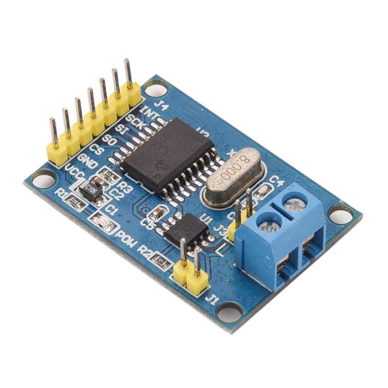 NiRen-MCP2515 CAN-Bus adapter (8Mhz) (Available in our Store) NiRen-MCP2515 CAN-Bus adapter (8Mhz) (Available in our Store) | |
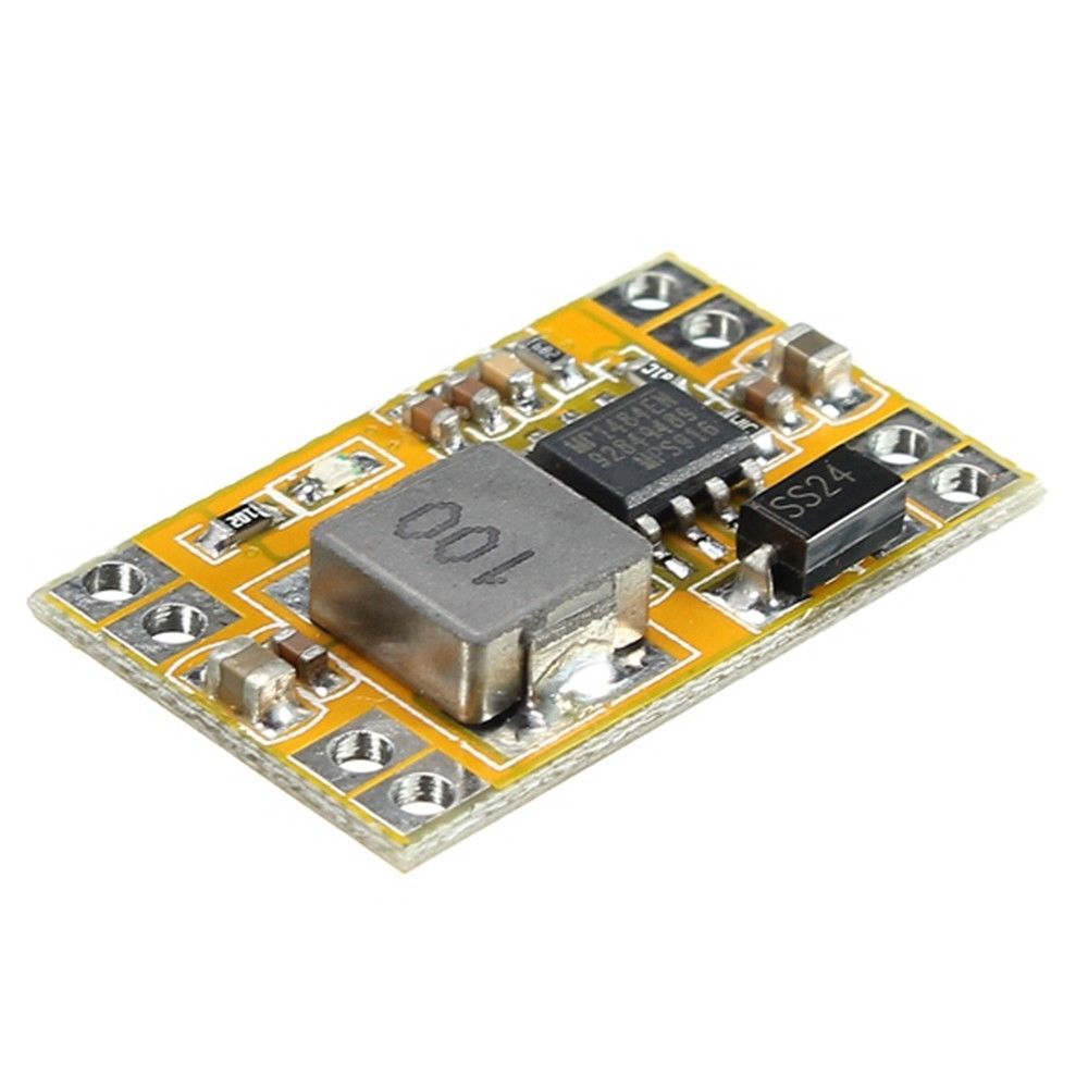 5V Voltage regulator [Fixed voltage is recommended, Adjustable can be installed] (Available in our Store) 5V Voltage regulator [Fixed voltage is recommended, Adjustable can be installed] (Available in our Store) | |
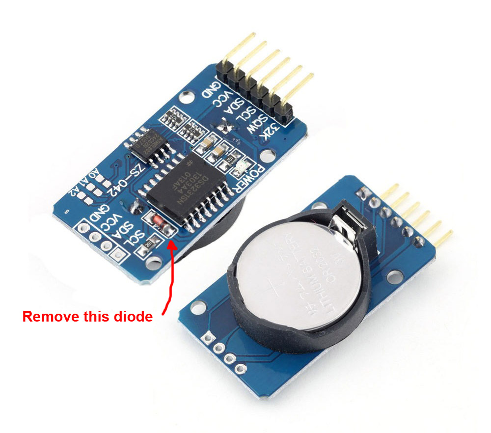 Real-Time Clock DS3231 unit (Available in our Store)Optionally, remove the diode that trickle-charges the battery. Real-Time Clock DS3231 unit (Available in our Store)Optionally, remove the diode that trickle-charges the battery. | |
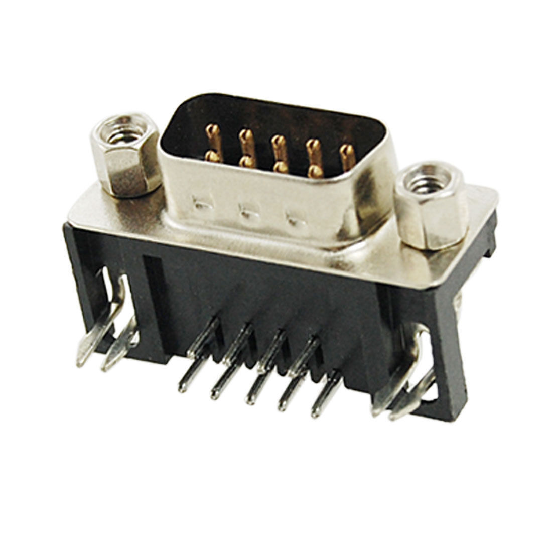 9-Pin D-SUB Male Right Angle connector (Available in our Store) 9-Pin D-SUB Male Right Angle connector (Available in our Store) | |
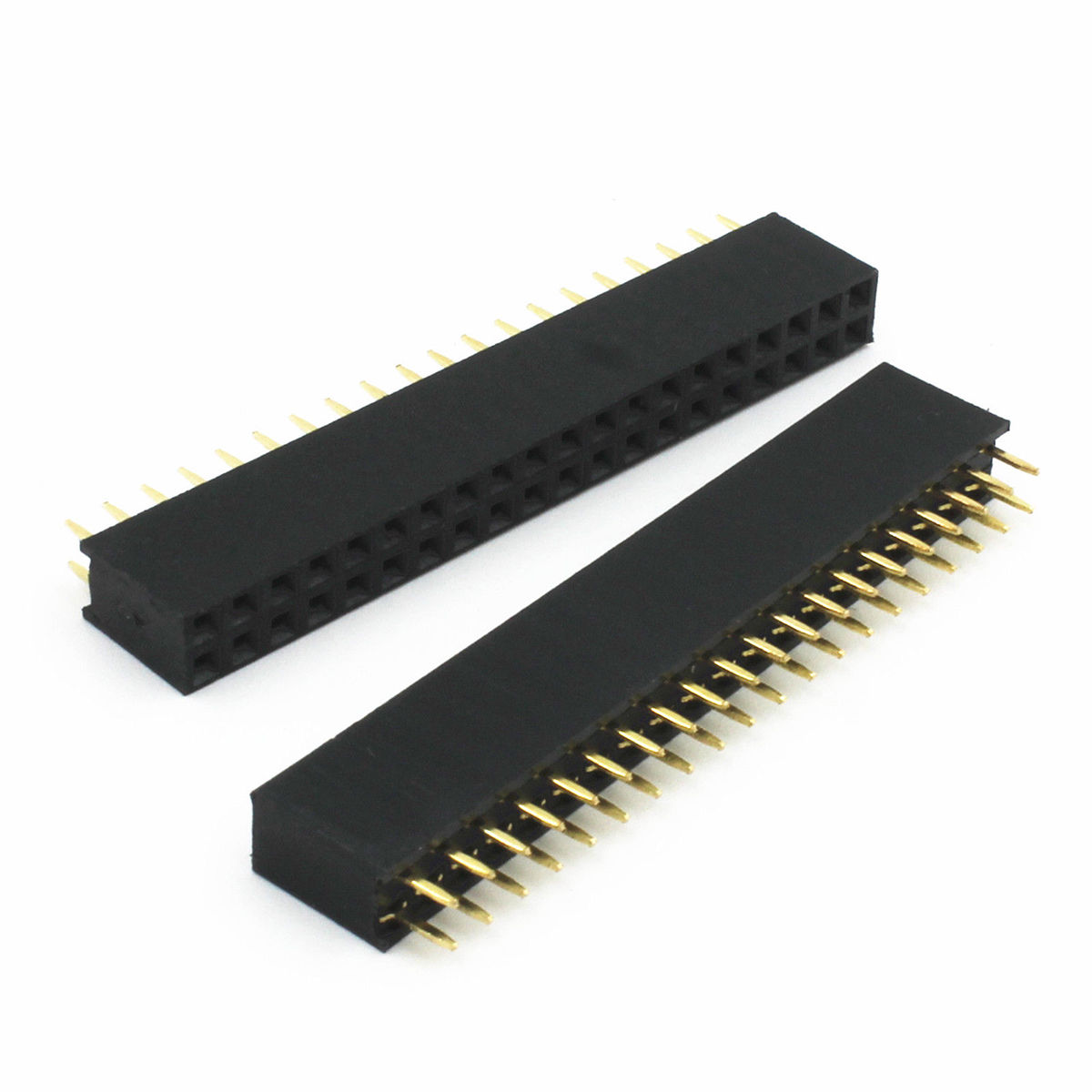 40-pin Female connector (Available in our Store) 40-pin Female connector (Available in our Store) | |
| Four 11mm bronze M3 standoffs |
Assembly Instructions
| # | Step |
| 1. | Prepare 4 male header pins by breaking away 4 individual pins from the longer strip and shortening the longer side of the pins to the same length as the the shorter ones. |
| 2. | Position the pins on main board and position the voltage regulator board on top of the 4 pins. |
| 3. | Holding the two boards aligned, solder the pins on the voltage regulator side first and then on the bottom side of the main board. |
| 4. | Prepare 4-pin male header strip by breaking it away from the longer strip and shortening the longer side of the pins to the same length as the the shorter ones. |
| 5. | Carefully straighten up the six angled pins on the RTC board. Use needle-nose pliers to straighten the pins. |
| 6. | Shorten the 6 pins to the same length as the pins we prepared at step 4 |
| 7. | Position the 4-pin strip on the main board and position the RTC board on top of them with the 6 pins passing through the holes on the main board. |
| 8. | Holding the two boards aligned, solder the pins on the RTC side first and then on the bottom side of the main board. |
| 9. | Remove the screw terminal from the MCP2515 CAN-Bus adapter |
| 10. | Cut the terminating resistor pins |
| 11. | Shorten the MCP2515 CAN board by about 5-6 mm from the side where screw terminal was installed. Make sure the CAN board and the 9-pin male D-Sub connectors fit on the PCB board without touching each other. This is especially important if straight DB9 connector is used. |
| 12. | Install and solder the CAN board to the main board. Make sure the CAN board components don’t touch the main board surface. |
| 13. | Install and solder the DB9 male connector (straight or angled, depending on how the board meant to be mounted in the avionics compartment. |
| 14. | Install and solder the 2-row 40-pin female header on the bottom side of the main board. |
| 15. | Install the four 11mm bronze standoffs on the bottom side of the main board with a nylon washer between each standoff and the board. Use 6mm M3 screw. Do not tighten the screws until after the unit is fully assembled. |
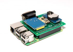
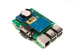
| 16. | Connect the main board to the Raspberry Pi board |
Software installation instructions:
- Install Raspbian – Raspberry Pi Operating System (NOOBS) (https://www.raspberrypi.org/documentation/installation/)
You will need a monitor, keyboard and mouse connected to the board.
It would be good to have the RPi connected to your local wired network (LAN) now.
You can power the RPi board via USB or connect it to the FDR unit and power it via CAB-Bus
Keep the RPi connected to the display and keyboard for the next step. - Configure Network Interfaces (Instructions)
- Configure network share service (Samba) (Instructions)
- Configure Real-Time clock (Instructions)
- Install SQLite (Instructions)
- Configure the space for the messaging database (Instructions)
- Configure CAN-Bus interface (Instructions)
- Install and Configure CAN_Listener [Python] (Instructions)
- Install and Configure the “Glass Panel” dashboard [Node.js] (Instructions)
- Creating a shortcut for the Glass Panel on iPad desktop (Instructions)
- Install and Configure the Data Logger (FDR) (Instructions)
- Install and Configure Voice Warning system “Betty” [Python] (Instructions)
- Install and Configure ADS-B interface (Instructions)
- Install and Configure USB GPS unit (Instructions)
Schematics & PCBs
FDR, ADS-B, GPS, Tablet Display unit schematic (PDF): FDR_ADS-B_GPS_Raspbery_Pi_Schematic
FDR, ADS-B, GPS, Tablet Display unit schematic DipTrace (.zip): RPI_DISPLAY_FDR_v22_Schematic_DipTrace
FDR, ADS-B, GPS, Tablet Display PCB DipTrace (.zip): RPI_DISPLAY_FDR_v22_PCB_DipTrace
FDR, ADS-B, GPS, Tablet Display PCB Gerber (.zip): RPI_DISPLAY_FDR_v22_PCB_gerber
ToDo/FixIt
| # | Description |