EMS
 Engine Management System
(aka Engine Information System)
Updated: July 19, 2023
Design overview:
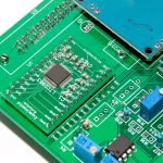
The idea behind this project is to create a hardware platform for continuous development and improvement of the Engine Management System through software. So, you might notice that many components in the schematic and PCB are optional and different components might be used depending of the purpose of a sensor.
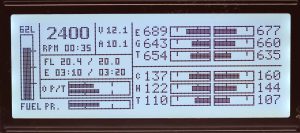
The hardware designed to monitor 18 different engine parameters, including 8 temperature sensors (4-cylinder version) at very high precision (24 bits), 8 resistive sensors at 10 bits precision, two pulse-based parameters (RPM and Fuel Flow) and one discrete input.
Not all inputs are configured in the software at this stage, but the hardware provides a very flexible platform to meet large variety of requirements for engine monitoring in experimental aviation. The unit can be used for automotive engines as well.
Parameters configured to monitor and display:
- RPM
- Engine timer (Tacho timer)
- Oil Temperature
- Oil Pressure
- Fuel level
- Fuel Pressure
- Fuel Flow
- EGT X 4 (Type K sensors)
- CHT X 4 (Type J thermocouples or Thermistors)
- Voltmeter
- Ampermeter x 2
- Endurance based on current fuel flow
- Endurance based on planned fuel flow
The EMS board communicates with the rest of the system via CAN bus. All the information sent to the display is also recorded by the Flight Data Recorder unit at the rate of 1 record per second.
The EMS built as a fully software driven and very flexible platform. The hardware has a lot of provision for lots of extra features. These will come later.
My test platform is Rotax 912 driven RV-12 aircraft. So the software will be biased towards Rotax engine. Nevertheless, the hardware can accommodate almost any 1 – 6 cylinder engine.
EMS consists of two physically separate modules connected together via CAN bus:
- Sensor Unit
- Display Unit
Sensor Unit
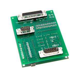
Board size 100mm X 100mm.
Key components:
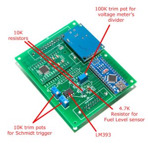
- 16 Mhz ATmega328 processor (Arduino Nano),
- LTC2983 thermocouple management chip from Linear with 24-bit ADC.
- MCP2515 CAN chip (NeRen CAN breakout board)
CAN controller is a breakout board from eBay based on MCP2515 chip. I had to cut it a bit to save some space on the main board.

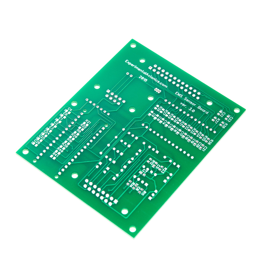

Parts list:
| Schematics Reference | Part Name |
| ARD1 | 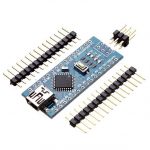 Arduino Nano (Available in our Store) Arduino Nano (Available in our Store) |
 EMS Module PCB Board (Available in our Store) EMS Module PCB Board (Available in our Store) | |
| MCP2515 |  NiRen-MCP2515 CAN-Bus adapter (8Mhz) (Available in our Store) NiRen-MCP2515 CAN-Bus adapter (8Mhz) (Available in our Store) |
| U2 |  LM393 Dual Comparator (Available in our Store) LM393 Dual Comparator (Available in our Store) |
| LTC2983 | 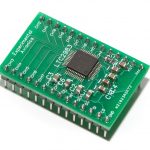 LTC2983 breakout board (Available in our Store) LTC2983 breakout board (Available in our Store) |
| U3 | D-Sub connector 25 pins, Female. Amphenol D25S24B6GV00LF or similar |
| U4 | D-Sub connector 9 pins, Male. Amphenol D09P24B6GV00LF or similar |
| U5 | D-Sub connector 15 pins, Male. Amphenol D15P24B6GV00LF or similar |
| C1-C4, C6, C7, C9, C10, C14 – C26 | 0.1 uF capacitors for thermocouples and ADC low-pass filter. SMD size 0805 |
| C5, C8 | 100pF capacitor for Schmidt trigger low-pass filter. SMD size 0805. Optional. |
| R8, R19 – R22, R26, R27, R29 – R41 | 6.8K resistors for thermocouples and ADC low-pass filter. SMD size 0805. |
| R5, R6 | 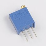 10K Trimpot for Schmidt trigger threshold adjustment 10K Trimpot for Schmidt trigger threshold adjustment |
| R17, R18 |  10K resistor 10K resistor |
| R1, R2 |  1K – 10K resistor for resistive sensors. Choose the value that together with the maximum resistance of the sensor form a 1:5 voltage divider. 1K – 10K resistor for resistive sensors. Choose the value that together with the maximum resistance of the sensor form a 1:5 voltage divider. |
| R15, R16 |  10K pullup resistor for the Schmidt trigger. Optional 10K pullup resistor for the Schmidt trigger. Optional |
| R11, R23 | 1M resistor. SMD size 0805 |
| R12, R14 | 10K resistor. SMD size 0805 |
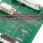
| R3, R4, R7, R9, R10, R24 |  100K or 1M trimpot to form voltage divider for measuring voltage output of the sensors. Adjust to take the maximum voltage value on the central pin to 1.1V. If you want to use the input for resistive sensors, instead of trimpot install a pullup resistor (just like R1, R2), one leg into the additional hole next to the trimpot marking and the other into the nearest hole of the trimpot marking, shortening it with the centre hole. 100K or 1M trimpot to form voltage divider for measuring voltage output of the sensors. Adjust to take the maximum voltage value on the central pin to 1.1V. If you want to use the input for resistive sensors, instead of trimpot install a pullup resistor (just like R1, R2), one leg into the additional hole next to the trimpot marking and the other into the nearest hole of the trimpot marking, shortening it with the centre hole. |
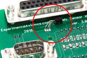
| Q1 | Cold junction temperature sensor. I use transistor BC547. A diode can be used instead. Install it in a way so its body makes physical contact with the body of the 25-pin D-Sub connector. |
Assembly Instructions
Notes on sensors
| Sensor | Notes |
| EGT | . |
| CHT | . |
| Oil Pressure | Reference sensor: Honeywell PX3AN1BH150PSAAX Reference Engine: Rotax 912ULS Sensor range: 0 to 150 PSI (0 – 10 Bar) Sensor response: voltage 0.5 – 4.5v proportional to pressure 0 – 150PSIPressure limits for the reference engine: Red: < 0.8 Bar (0 – 12 PSI) Yellow: 0.8 – 2 Bar (12 – 30 PSI) Green: 2 – 5 Bar (30 – 73 PSI) Yellow: 5 – 7 Bar (73 – 100 PSI) Red: >7 Bar (>100 PSI) |
| Oil Temperature | Reference Sensor: ???? 0-150C Reference Engine: Rotax 912 ULS Sensor Range: 50 – 150 Sensor response:Temperature limits: Red: < 50C Yellow: 50C – 80C Green: 80C – 110C Yellow: 110C – 140C Red: >140C |
| Fuel Pressure | . |
| Coolant Temperature | . |
| Alternator’s Current | . |
| Battery’s Current | . |
| . | . |
Connectors pinout (boards ver. 4.0):
| U3 – Thermocouples terminal 25 pins (this terminal is for LTC2983 inputs only) (TC – thermocouple) The mapping between pins and channels is fixed (this is how the pins are wired on PCB) The mapping between channels and sensors is defined in the software. |
|
| Pin | Function |
| 1 | Channel 1 – EGT1 TC Negative |
| 2 | Channel 3 – EGT2 TC Negative |
| 3 | Channel 5 – EGT3 TC Negative |
| 4 | Channel 7 – EGT4 TC Negative |
| 5 | Channel 9 |
| 6 | Channel 11 |
| 7 | Channel 13 |
| 8 | Channel 15 |
| 9 | Channel 19 |
| 10 | Channel 17 |
| 11 | +5V |
| 12 | Ground. |
| 13 | Ground. |
| 14 | Channel 2 EGT1 TC Positive |
| 15 | Channel 4 EGT2 TC Positive |
| 16 | Channel 6 EGT3 TC Positive |
| 17 | Channel 8 EGT4 TC Positive |
| 18 | Channel 10 – Single-ended temp. sensor for cyllinder 1 |
| 19 | Channel 12 – Single-ended temp. sensor for cyllinder 2 |
| 20 | Channel 14 – Single-ended temp. sensor for cyllinder 3 |
| 21 | Channel 16 – Single-ended temp. sensor for cyllinder 4 |
| 22 | Channel 18 |
| 23 | +5V |
| 24 | +5V |
| 25 | Ground. |
Notes:
|
|
| U5 – Sensors inputs 15 pins (Analog inputs A0-A7 for Arduino Nano) |
|
| Pin | Function |
| 1 | Alternator Ammeter A1. Voltage meter via R9. |
| 2 | Main power bus voltage A0. Voltage meter via R10 |
| 3 | RPM Pulse input 1. (D2, INT0) |
| 4 | Fuel Flow. Pulse input 2. (D3, INT1) |
| 5 | Oil Pressure A3. |
| 6 | +5V |
| 7 | Fuel Level A2. Resistive sensor via R1 (4.7k) |
| 8 | GND |
| 9 | D7. Digital input or output. |
| 10 | Fuel Pressure A4. Voltage via R7. |
| 11 | Battery Ammeter A7. Voltage via R24. |
| 12 | Whatever you want (Second fuel tank, manifold pressure, coolant temp., etc) A6. Voltage via R3. |
| 13 | +5V. |
| 14 | Oil Temperature A5. Voltage via R4. |
| 15 | GND |
| U4 – CAN-Bus 9 pins | |
| Pin | Function |
| 1 | |
| 2 | CAN-Low |
| 3 | GND (Power -) |
| 4 | |
| 5 | |
| 6 | |
| 7 | CAN-High |
| 8 | |
| 9 | Vin (Power +) |
Software Download
The latest version of software (Arduino) is available at GitHub https://github.com/ExperimentalAvionics/EMS_Sensor
Make sure to set CYL variable according to the number cylinders of your engine. (Line 20 in the EMS_Sensor.ino)
Currently supported values are 6 – for the 6-cylinder sensor board and 4 – for the 4 cylinder sensor board.
Also ensure the same CYL value set for the Display Unit software.
New to GitHub? – Here is a quick GitHub guide.
The software needs to be adjusted according to your engine, electric and fuel system setup.
New to Arduino? –
- Go to YouTube
- Search for “upload program to arduino”
- Watch a couple of videos on how to load the software into Arduino Uno.
The workflow for other Arduino boards (Mega, Nano, etc) is practically identical.
Schematics and PCBs
Main EMS Board
EMS Schematic (PDF): EMS Schematic (PDF)
EMS Schematic DipTrace (.zip): EMS_Sensor_v40_Schematics
EMS board PCB DipTrace (.zip): EMS_Sensor_v4-4c_DipTrace
EMS board PCB Gerber (.zip): EMS_Sensor_v4-4c_gerber
LTC2983 Breakout Board
LTC2983 Breakout Board Schematics (PDF): LTC2983_Breakout_Board_Schematics_PDF
LTC2983 Breakout Board Schematics (DipTrace .zip) LTC2983_Breakout_Board_Schem_DipTrace
LTC2983 Breakout Board PCB Gerber (.zip): EMS_LTC2983_Adapter_v2_gerber
LTC2983 Breakout Board PCB DipTrace (.zip): EMS_LTC2983_Adapter_v2_diptrace
ToDo/FixIt
| # | Description | Status |
| 1. | Todo: Create a version of the PCB for differential connections for the thermocouples for 4-cyl or smaller engines. | Done. Termocouples connected in differential mode. Accuracy improved significantly. |
| 2. | Add LEDs at the outputs of the comparator to indicate when pulse sensor is tuned properly | |
| 3. | Add a separate ADC with an extra connector for sensors with enough +5v pins | |
Update August 2024


