CAN-HUB
Updated: June 20, 2023
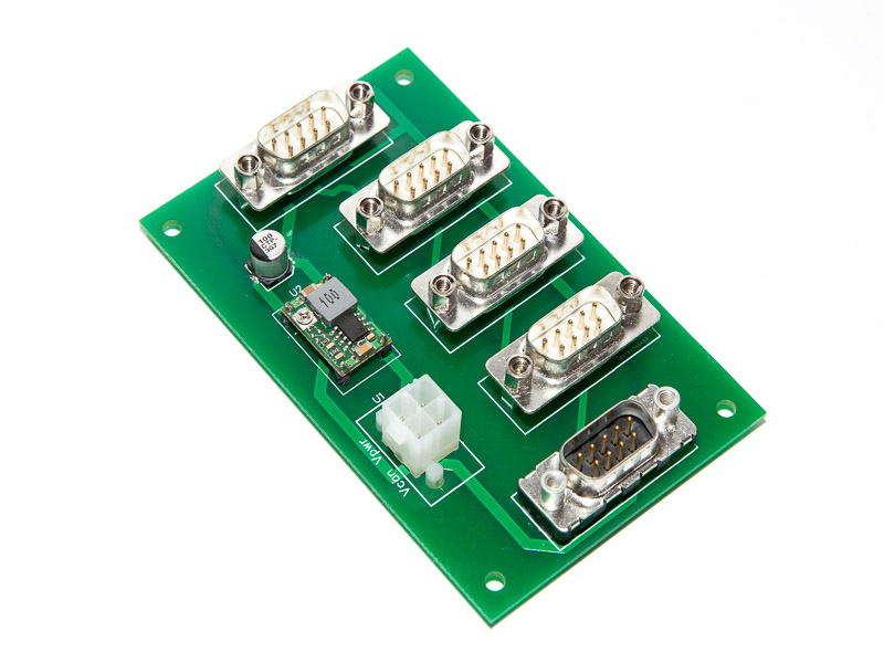
The purpose of the CAN-HUB is to provide the power to all the units in the network and allow for simple universal interconnection between units. Although the Arduino based units can be powered directly from the aircraft main power bus (+12..+14v), it is better to reduce the voltage to +6.8..7.0v to improve power efficiency.
The CAN-HUB unit has been redesigned recently to have a separate D-Sub connector for the Raspberry Pi based unit (FDR, tablet “glass panel”, etc). The unit consumes the lion share of the power due to various USB based devices attached to it. It does have its own power supply circuit on the FDR board, so it better to power it directly from the aircraft main power bus and reduce the load on the power regulator that controls the input voltage for Arduino-based units.
A new version of the CAN-HUB is available now. See the Backup Power page for details.
The new version supports backup battery to comply with Night VFR requirements (60 minutes of power in Australia)
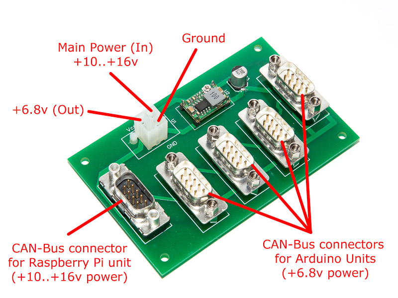
Voltage supplied via the U3-U6 (White) connectors for Arduino should be adjusted to 6.8 – 7 volts using the trim-pot on the power regulator.
Voltage supplied via the U7 (Black) connector is equal to aircraft main power bus (~14v)
There is no danger in connecting Arduino boards to Black connector or Raspberry Pi to the White ones. It will just reduce the power efficiency of the system and might make the on-board Arduino linear power regulators running hot.
The hub has 5 ports with D-Sub 9-pins connectors.
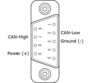
CAN-Bus connector pin-out:
Pin 2: CAN-Low
Pin 3: Ground (-)
Pin 7: CAN-High
Pin 9: Power (+)
When planning the wiring for your aircraft keep in mind that it is preferable to connect all the units in “chain” keeping the stubs as short as possible (under 0.5m). So if possible, minimise the number of direct connections from the units to the CAN-HUB board. Chain-up the units whenever you can.
The diagrams below illustrate the options of direct connections to the CAN-HUB and the chain-up connections. The direct connection option is easier to manage and so far worked very well. The chain-up option is more “canonical” however it might make the wiring a bit cumbersome.
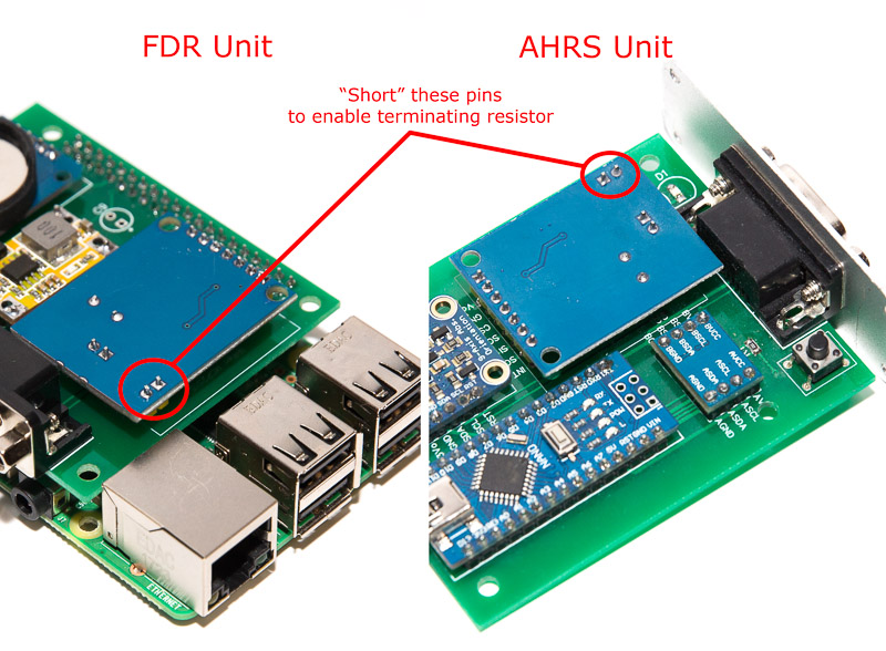
Please note, that in both cases the terminating resistors on the units at the both ends of the CAB-Bus should be enabled (FDR and AHRS units). The resistor enabled by shorting the relevant pins on the CAN adapter.
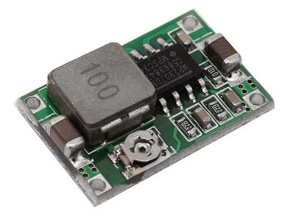
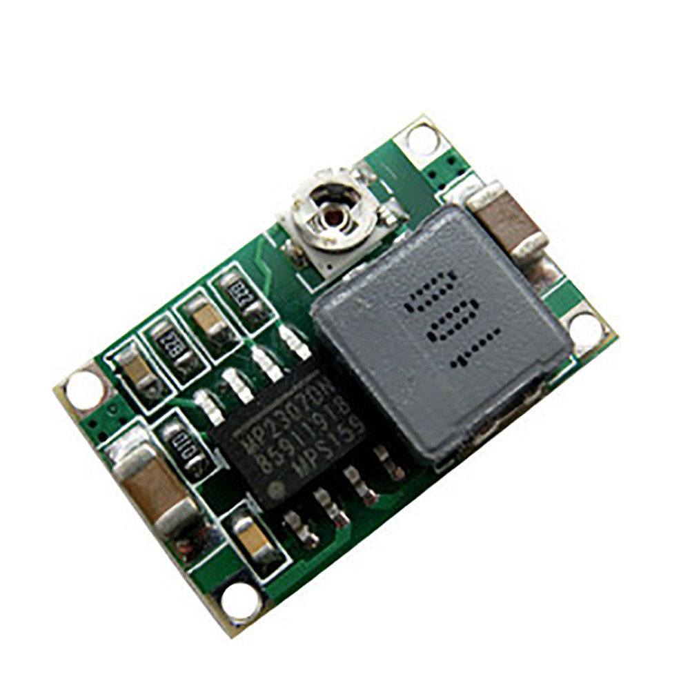
Voltage regulator unit is a miniature adjustable DC-DC Buck converter, based on MP2307DN chip, that can be purchased from our Store or from eBay. The unit provides reasonably clean output with large range of input voltage 7-23v.
The output voltage should be set to about 6.8v to allow for maximum efficiency and stability of the system.
For very noisy power lines a low-ESR electrolytic capacitor can be added on each side of the power supply unit.
Parts list:
| Schematics Reference | Part Name |
 CAN-HUB PCB Board (ver 2) (Available in our Store) CAN-HUB PCB Board (ver 2) (Available in our Store) | |
 Adjustable Voltage regulator Adjustable Voltage regulator | |
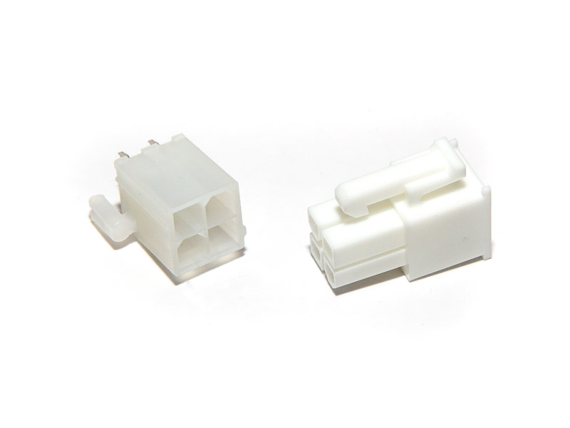 4-Pin Molex Mini-Fit Jr connectors pair 4-Pin Molex Mini-Fit Jr connectors pair | |
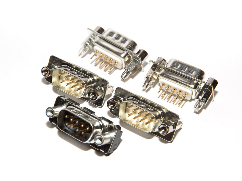 9-Pin D-SUB Male straight connectors, 5 pcs 9-Pin D-SUB Male straight connectors, 5 pcs | |
| Electrolytic capacitor 10-50 uF x 16v
Note: Do not install while the system is being tested. When individual units are powered via USB while connected to CAN HUB board, short reverse current into the discharged capacitor can damage the voltage regulator on Arduino Nano board. |
Assembly instructions
- Solder the Molex connector
- Solder the Voltage Regulator
- Power the unit via the Molex connector with 10-15v and measure the voltage on the pads of the optional C3 capacitor. Adjust the voltage to 6.8v using the trimpot on the voltage regulator.
- Solder the DB9 D-Sub connectors
Software
Software is not required for this unit
Schematics
Coming soon
ToDo/FixIt
| # | Description |