Trim Position Indicator
Updated: September 03, 2020
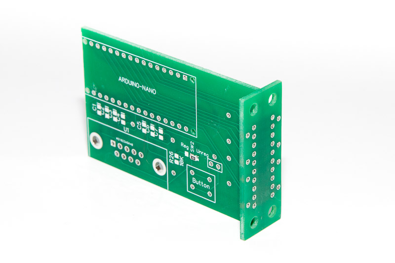
The trim indicator uses the same circuit board (PCB) as the Angle of Attack indicator except the pressure sensors.
The unit designed to work with Ray Allen trim servos. Position sensor on these servos is a simple potentiometer, so the indicator simply measures the voltage on the wiper.
Indicator does not require calibrated power for the position potentiometer. Instead it uses the main ship power and normalises the sensor input to account for any voltage fluctuations.
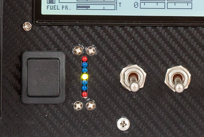
Neutral (for takeoff) trim position indicated by Green LED. Blue and Red LEDs indicate deviation from the neutral position.
When the servo is activated, the relevant Red LED is flashing.
The indicator needs to be calibrated if the takeoff trim position is not exactly in the middle of servo position. See calibration procedure below.
The unit reliably indicates position of the trim servo regardless of power fluctuations between +6 and +21 volts.
Connector pinout
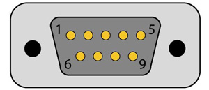
| Pin | Description |
| 1 | Ground |
| 2 | Trim Down button sensor |
| 3 | Trim Up button sensor |
| 4 | Trim position sensor |
| 5 | Not connected |
| 6 | Power +12v (internally connected to pin 7) Important: same power rail as the servo |
| 7 | Power voltage sense. (Connect it to pin 6 on the board) |
| 8 | Not connected |
| 9 | Not connected |
Connection diagram
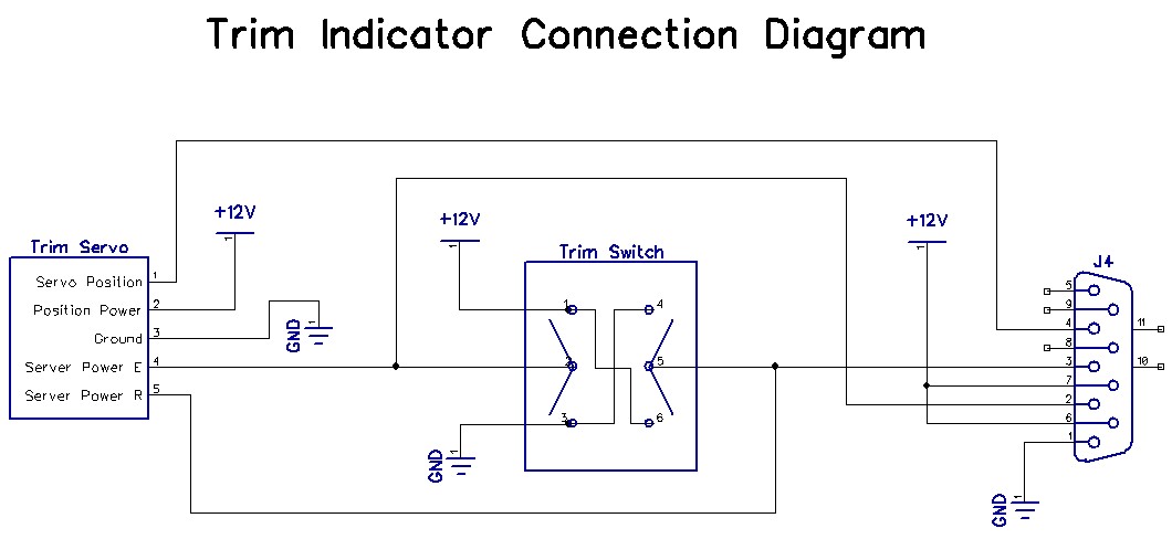
Trim Indicator Connection Diagram – PDF file
I used OTTO K2ABMAAAAA rocker switch to control trim motor.
Parts list:
| Schematics Reference |
Part Name |
 Arduino Nano (Available in our store) Arduino Nano (Available in our store) |
|
 LED Display PCB Board (Available in our store) LED Display PCB Board (Available in our store) |
|
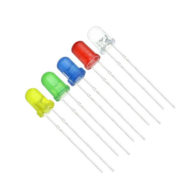 LEDs 3mm: 1 x Green, 4 x Blue, 2 x Red (Available in our store) LEDs 3mm: 1 x Green, 4 x Blue, 2 x Red (Available in our store) |
|
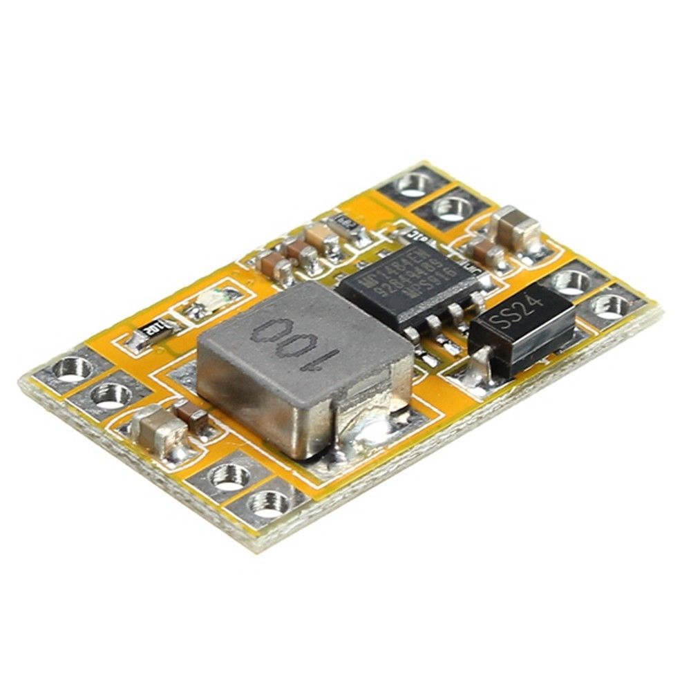 Switch-mode 5 volts power adapter Switch-mode 5 volts power adapter |
|
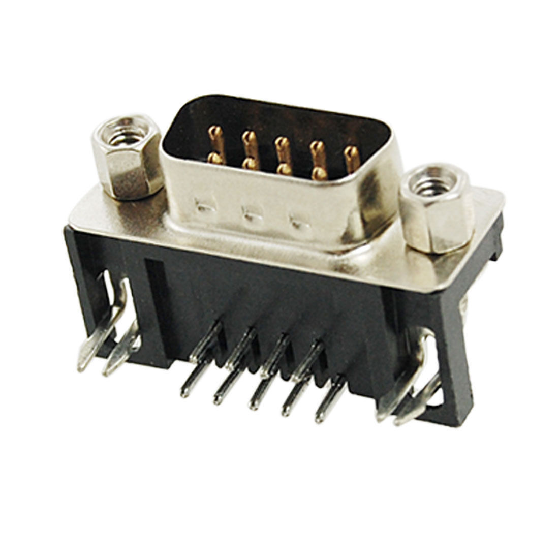 9-Pin D-SUB Male Right Angle connector (Available in our store) 9-Pin D-SUB Male Right Angle connector (Available in our store) |
Assembly Instructions
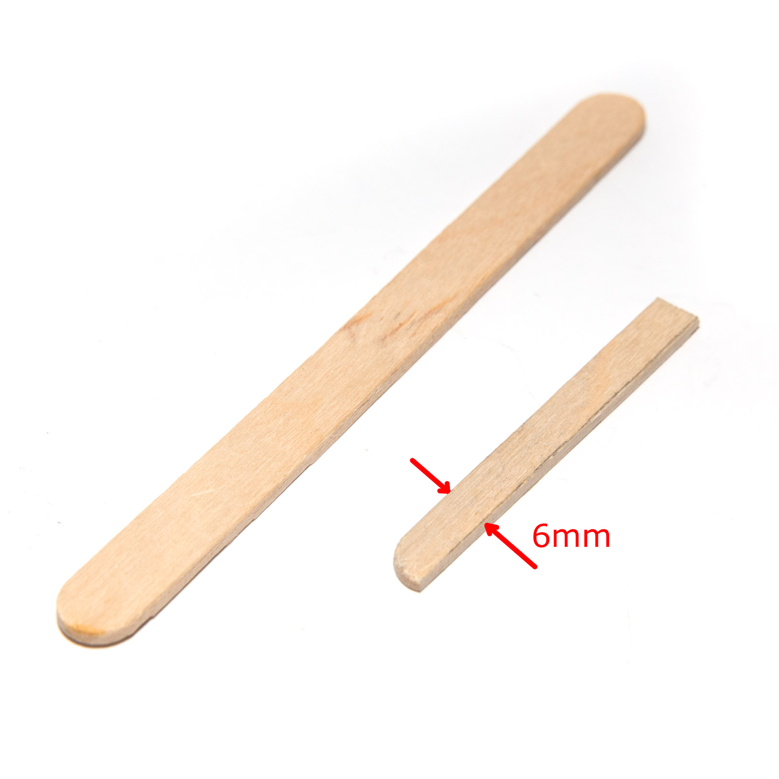
While assembling the unit please be careful not to break-off the T-connected PCB boards.
| Step | Instructions |
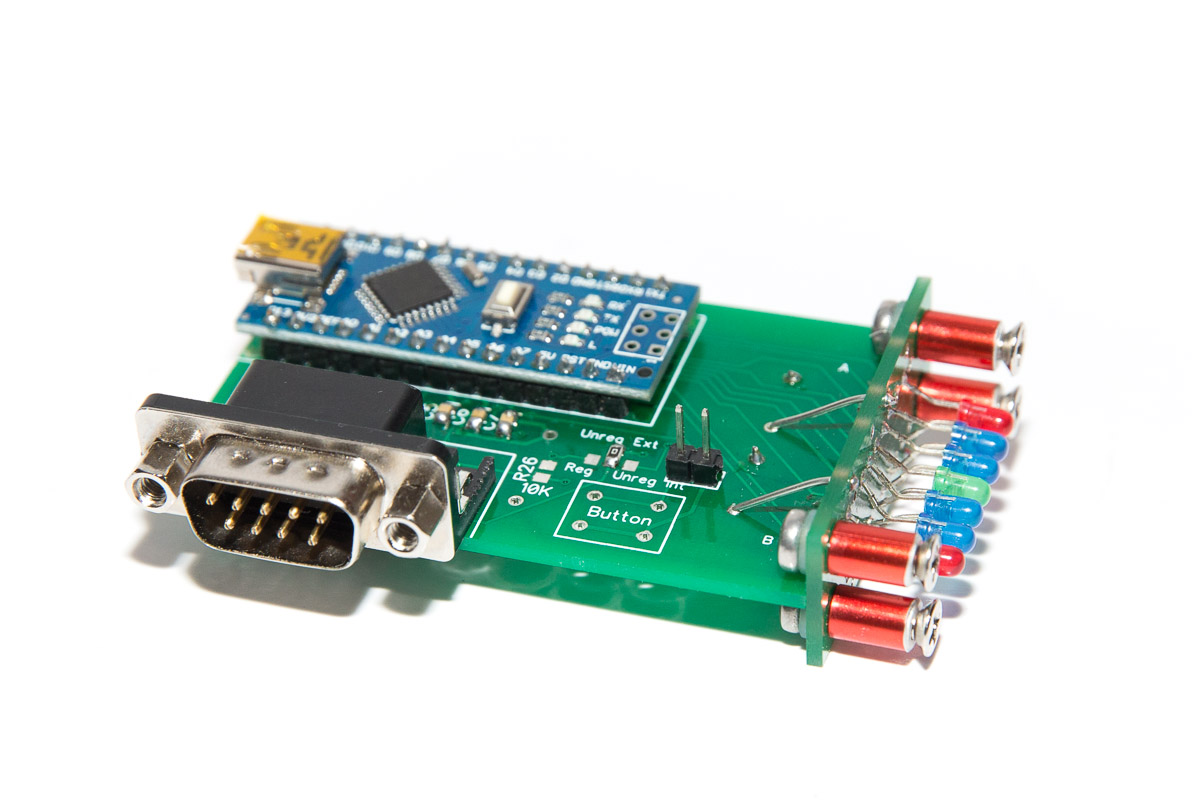
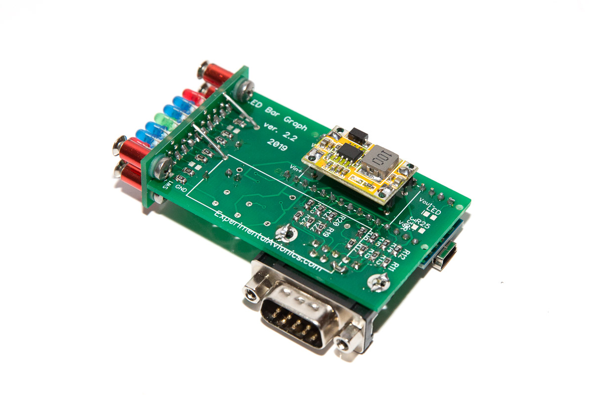
| 1 | Break out 4 individual header pins and use them to solder the yellow voltage regulator board to the main board. Make sure to keep about 5-6mm off-set between the main board and the voltage regulator board. Important! – make sure to complete this step before soldering the Arduino board |
| 2 | Prepare the two 15-pin headers for Arduino Nano by shortening the longer side to the same size as the shorter side. |
| 3 | Position the Arduino Nano on the main board and solder all the pins on both sides. |
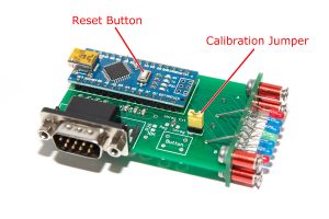
| 4 | Position and solder the 9-pin male D-Sub connector (see the picture above) |
| 5 | Install the 2-pin calibration header (see the picture above) |
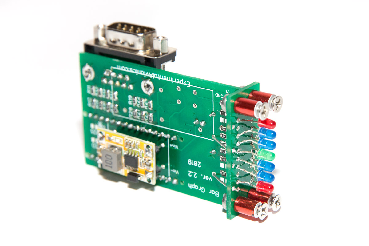
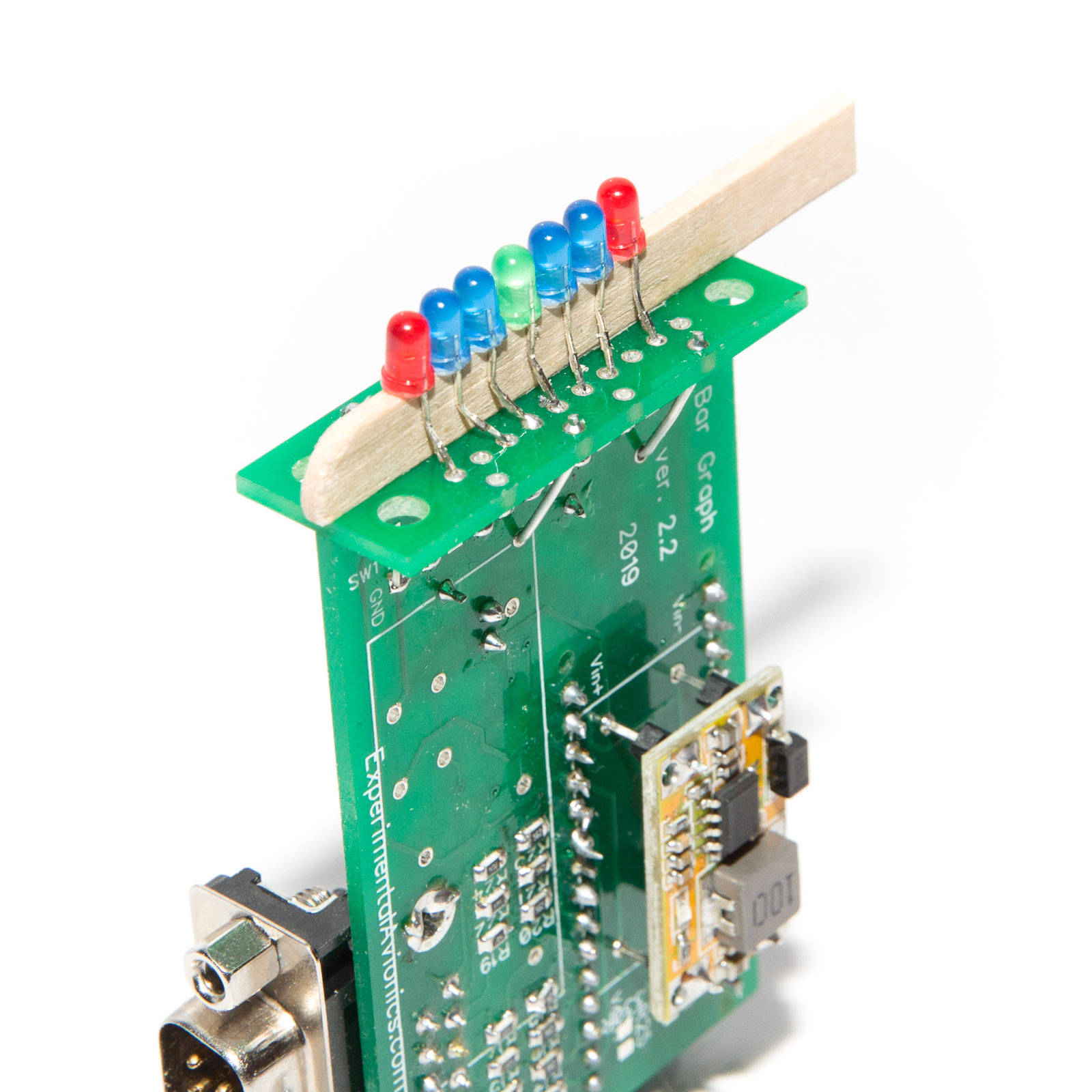
| 6 | 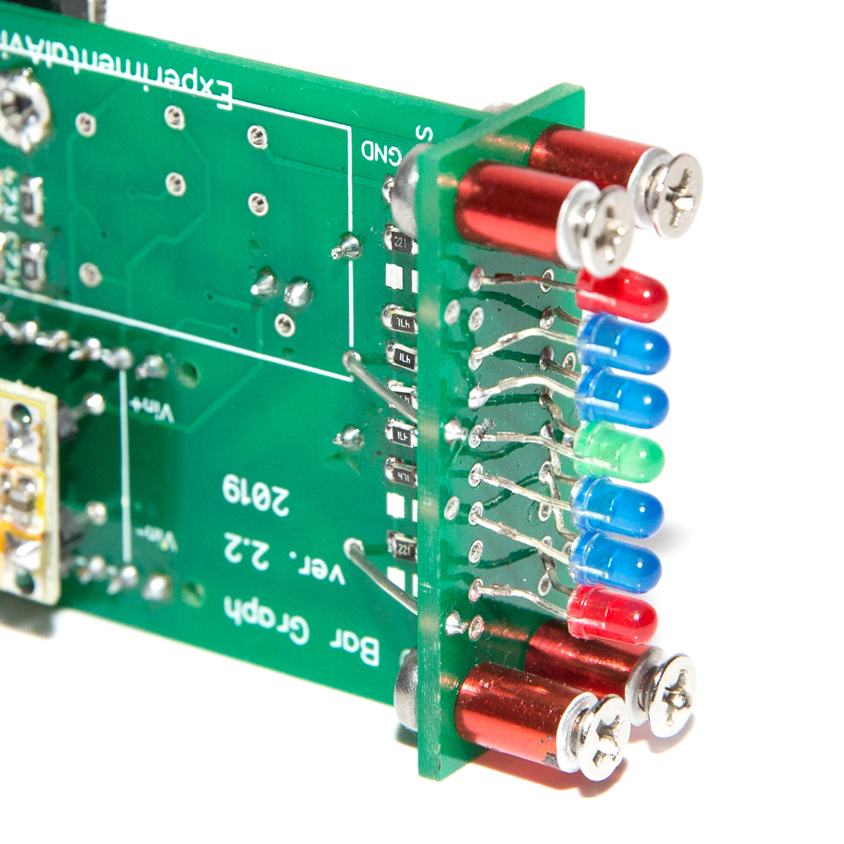 Install the LEDs. Make sure the LEDs positioned as per attached picture. Note that there are 10 pads for the LED while only 7 will be installed. Make sure some pads remain vacant as per picture.To ensure correct polarity of the LEDs make sure the flat side of LEDs is on side of the board where the yellow power converter is. Install the LEDs. Make sure the LEDs positioned as per attached picture. Note that there are 10 pads for the LED while only 7 will be installed. Make sure some pads remain vacant as per picture.To ensure correct polarity of the LEDs make sure the flat side of LEDs is on side of the board where the yellow power converter is.
I recommend to solder the LEDs last when you work out how and where the unit will be installed on the dashboard. |
| 7 | Optionally make reinforcing trusses by soldering 22 AWG wire in four places (see the pictures) |
| 8 | Upload the software |
Software
Download the software from GitHub: https://github.com/ExperimentalAvionics/Trim_Indicator
New to Arduino? –
- Go to YouTube
- Search for “upload program to arduino”
- Watch a couple of videos on how to load the software into Arduino Uno. The workflow for other Arduino boards (Mega, Nano, etc) is practically identical.
Uploading the software onto the Arduino Nano board
- Click on the link for software you want to download from my GitHub.
- Click on the “Clone or Download” button (Green button on the right hand side)
- Click “Download ZIP”. It will initiate the file download. The file name will be something like Trim_Indicator-master.zip
- Unzip the downloaded file into the folder where all your other Arduino projects are. On Windows it will be something like c:\Users\<MyName>\Documents\Arduino\
- The unzipped folder name will look like c:\Users\<MyName>\Documents\Arduino\Trim_Indicator-master. You need to rename it removing the “-master“.
So the folder name will look like this: c:\Users\<MyName>\Documents\Arduino\Trim_Indicator\ - Start your Arduino IDE, navigate to the folder you have just created and open up the Trim_Indicator.ino file. Note the name of the file to open is the same name as the name of the folder.
- Ensure the correct board is selected: Tools > Board > Arduino Nano
- Connect the Arduino board to your PC with a USB cable.
- Ensure the correct COM port selected: Tools > Port
- Press the “Upload” button.
- Wait for the code to be uploaded onto the Arduino board. Watch for the error messages at the bottom.
[/symple_tab][symple_tab title=”Calibration”]
 Move the trim in the neutral (takeoff) position (ignore the indication of the trim indicator).
- Short (connect together) the calibration pins using jumper cap.
- Press Reset button on Arduino board.
- Wait for the indicator having only Red LEDs on.
- Remove the jumper from the calibration pins. The indicator will exit calibration mode and resume normal operation.

Schematics
Trim Position Indicator Schematics (PDF)
ToDo/FixIt
| # | Description |
| 1 | |
| 2 | |
| 3 | |
| 4 |