EFIS Display Unit (ver. 3)
Updated: March 05, 2020
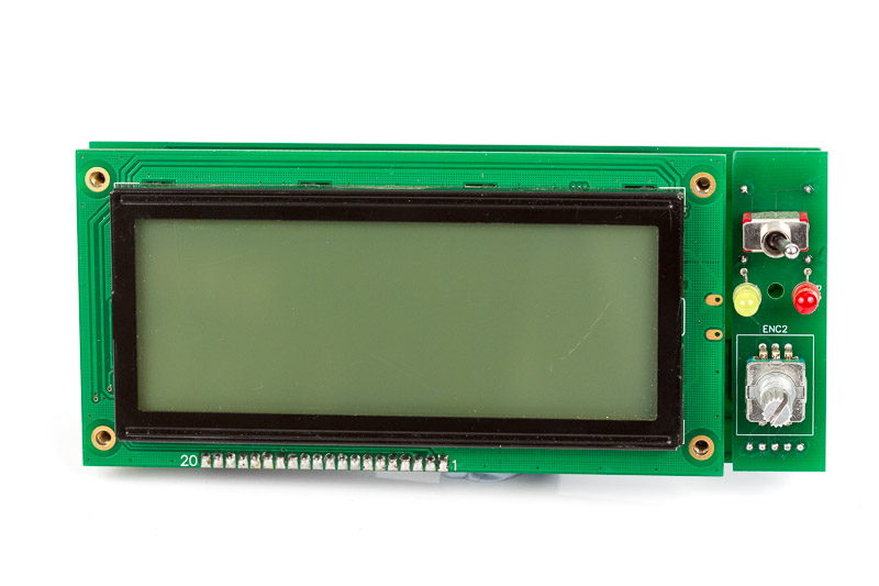
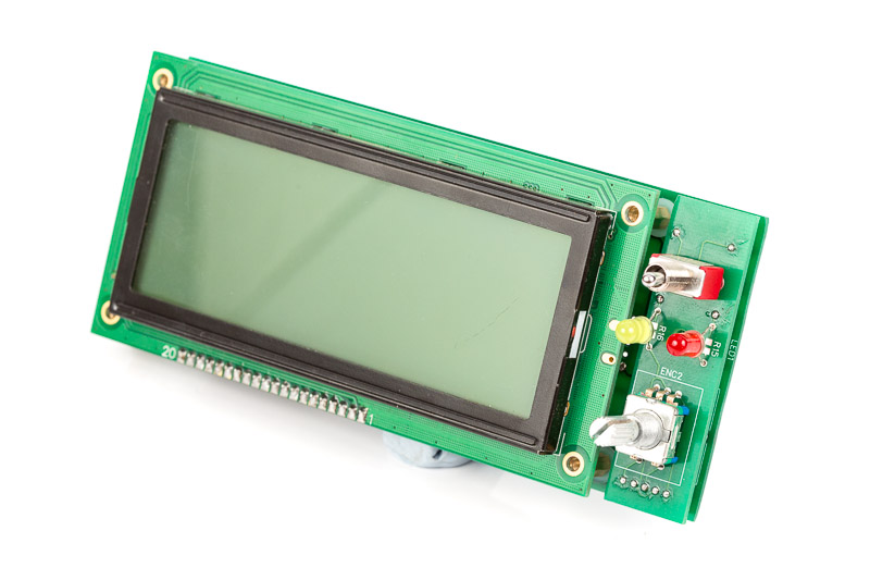
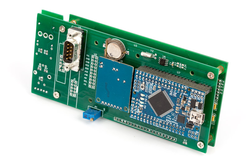
EFIS Display unit for ver 3 is an evolution of the previous versions of EFIS. Most of the changes related to physical layout of the PCB board and expansion connectors. Classic Arduino Mega board has been replaced with Arduino Mega Mini providing the same functionality and releasing some space for other components. The new PCB has an integrated RTC now, two different types of CAN connectors and an expansion connector for directly attached sensor boards. The changes allow much more convenient and robust installation on the instrument panel and improve the units versatility.
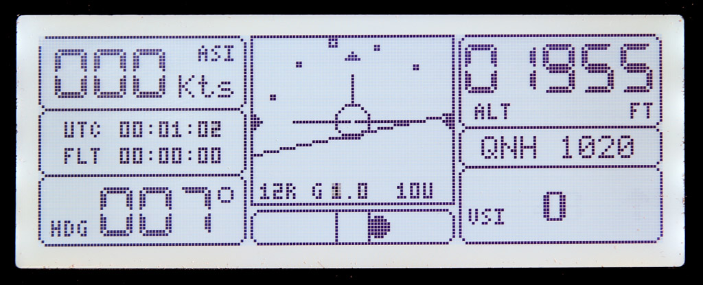
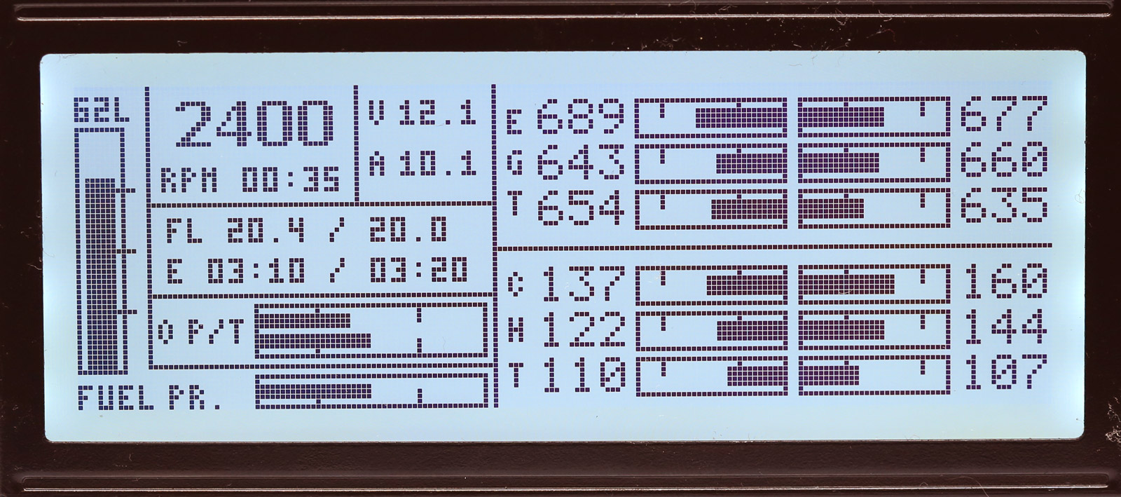
The software in the unit has changed quite a bit. The unit can now function as EFIS or EMS display. Just flick a switch and your EFIS turns into EMS in a fraction of a second. By having two identical display units on your dashboard you have full avionics set and full redundancy for your displays.
[symple_tabgroup][symple_tab title=”Parts list:”]
Parts list:
| Schematics Reference |
Part Name |
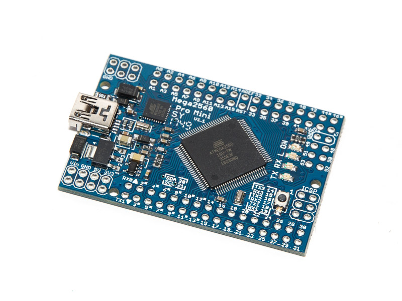 Arduino Mega 2560 Pro Mini (Available in our Store) Arduino Mega 2560 Pro Mini (Available in our Store) |
|
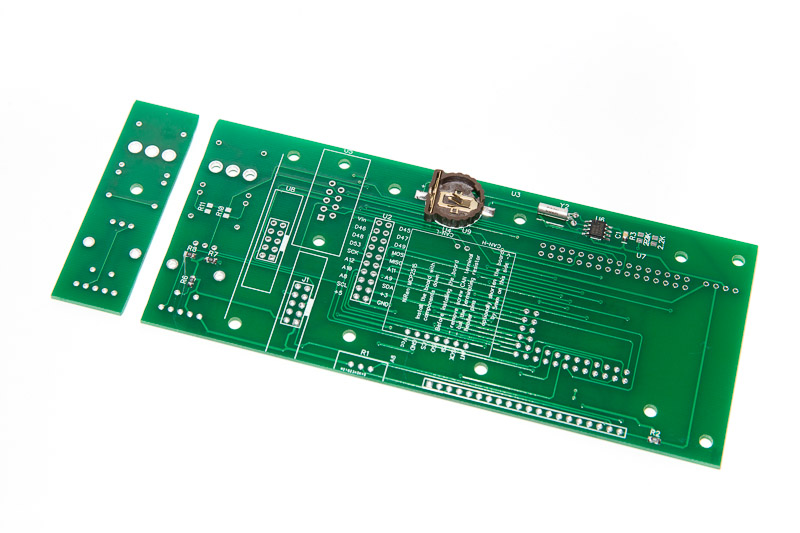 Display PCB Board (Available in our Store) Display PCB Board (Available in our Store)with all the required SMD components soldered on
|
|
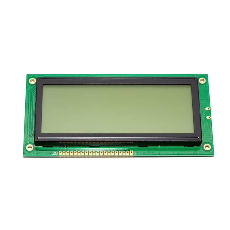 FSTN Display, 4″ 192×64 pix based on KS0107/KS0108 (Available in our Store) FSTN Display, 4″ 192×64 pix based on KS0107/KS0108 (Available in our Store) |
|
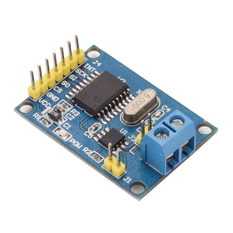 NiRen-MCP2515 CAN-Bus adapter (8Mhz) (Available in our Store) NiRen-MCP2515 CAN-Bus adapter (8Mhz) (Available in our Store) |
|
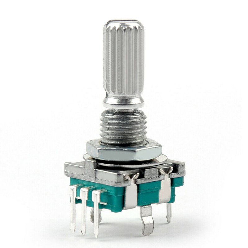 Rotary Encoder (Available in our Store) Rotary Encoder (Available in our Store) |
|
 10K potentiometer (trimpot) (Available in our Store) 10K potentiometer (trimpot) (Available in our Store) |
|
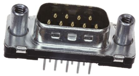 9-Pin D-SUB Male Straight connector 9-Pin D-SUB Male Straight connector |
|
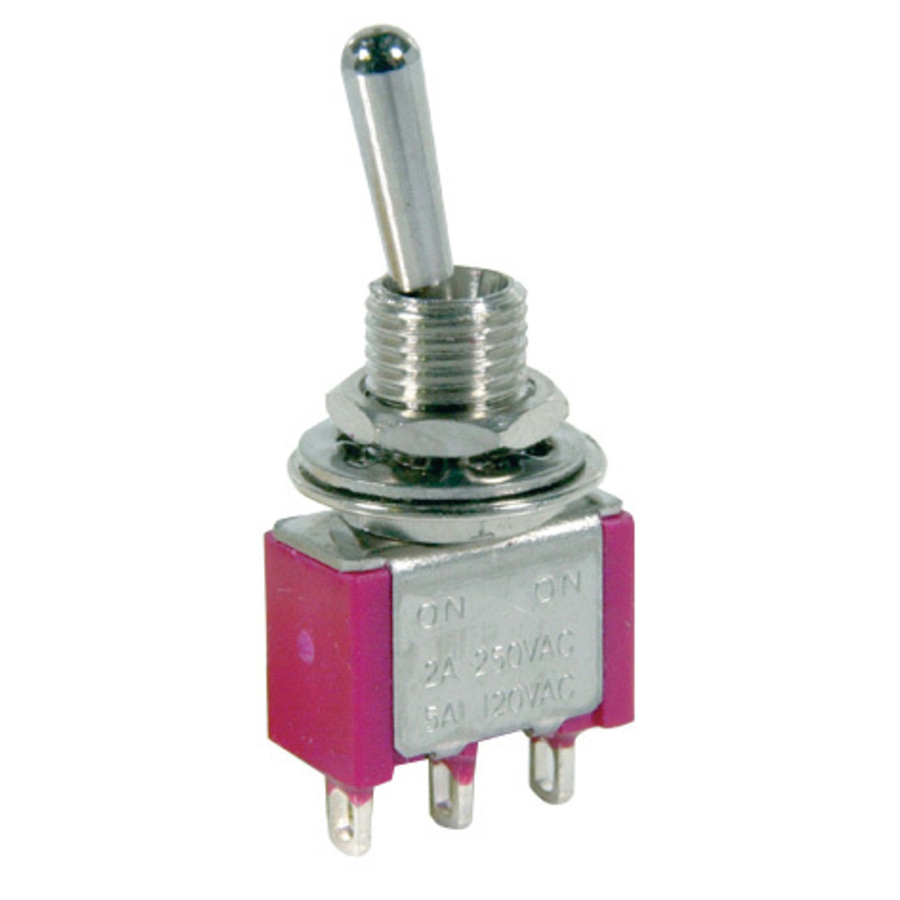 Toggle switch (optional) Toggle switch (optional) |
|
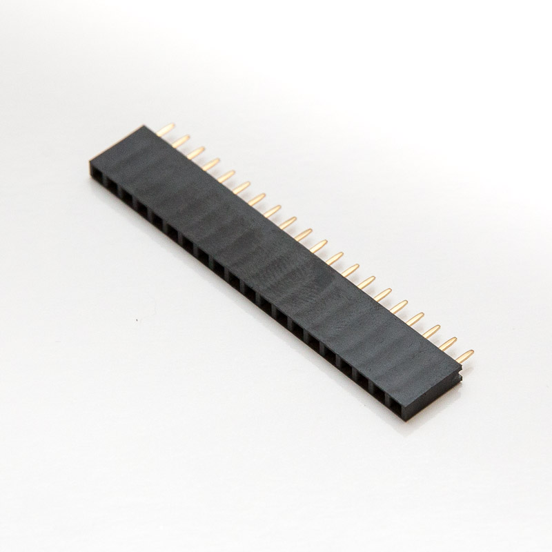 20-pin female header 20-pin female header |
|
 Five (5) 40-pin Male Header terminal strips. Five (5) 40-pin Male Header terminal strips. |
|
| U2 | 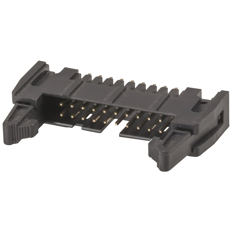 20-pin PCB-mounted Male locking IDC connector (optional) 20-pin PCB-mounted Male locking IDC connector (optional) |
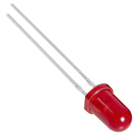 2 trough-hole LEDs and 2 appropriate SMD 0805 resistors (optional) 2 trough-hole LEDs and 2 appropriate SMD 0805 resistors (optional) |
|
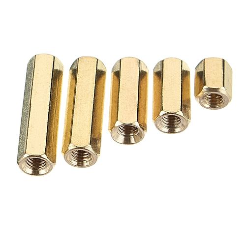 Four 11mm standoffs with M3 treads Four 11mm standoffs with M3 treads |
|
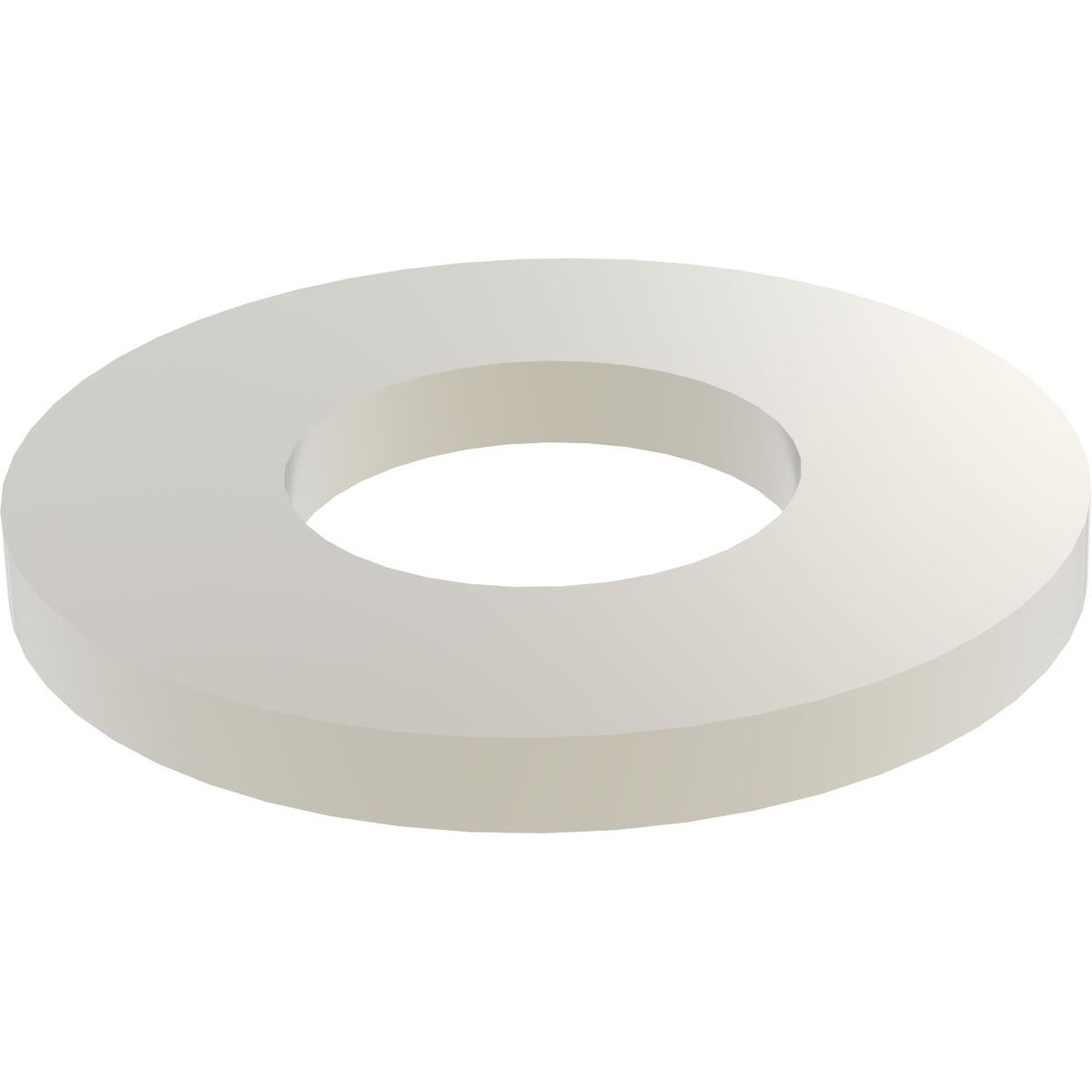 20 Nylon washers 1mm thick 20 Nylon washers 1mm thick |
|
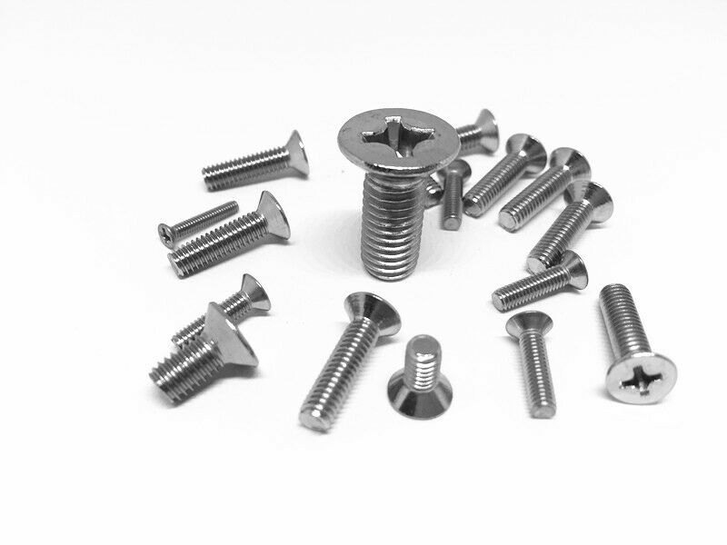 Four M3 bolts 12mm countersunk head Four M3 bolts 12mm countersunk head |
|
 Four M3 bolts 6mm button head Four M3 bolts 6mm button head |
[/symple_tab][symple_tab title=”Assembly Instructions”]
[symple_box color=”red” fade_in=”false” float=”center” text_align=”left” width=”100%”]Important note: There is a little error in the video at 13:03 – 13:05. The pins in this video placed in the wrong position. The correct position is the holes closest to the toggle switch holes. It doesn’t matter if you don’t use the LEDs.[/symple_box]
Detailed instructions for assembling the Display Unit
- Assemble the unit
- Prepare the male pins for soldering them to the main board
- Prepare the female headers for soldering them to the Arduino Mega Mini board
- Join the headers and boards together
- Solder the headers on the Arduino board
- Solder the pins on the bottom side of the main board
- Separate the Arduino board from the main board
- Remove the screw terminal from the MCP2515 CAN-Bus adapter
- Cut the terminating resistor pins
- Shorten the CAN board by about 5mm from the side where screw terminal was installed
- Install and solder the CAN board to the main board. Make sure the CAN board components don’t touch the main board surface.
- Install and solder the DB9 male connector.
- Install and solder the 20-pin female header on the bottom side of the main board.
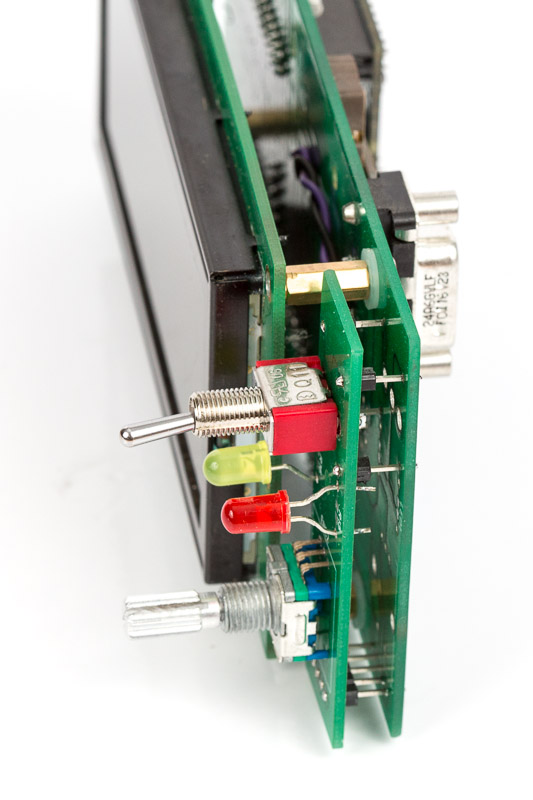
- install and solder the 20 pin male header on the LCD display
- attach the LCD display
- Install and solder the encoder on the spacer board
- (Optional) Install and solder the toggle switch on the spacer board
- (Optional) Install and solder the warning LEDs on the spacer board
- Install and solder the 9 male header pins on the bottom side of the spacer board
- install the spacer board on the main board. Before soldering it to the main board, it might be a good idea to trial-fit the unit into the instrument panel and see what is the best position for the spacer. If possible solder the spacer with the unit fitted.
- Upload the software
- Perform basic tests
- Install the unit on the instrument panel
[/symple_tab][symple_tab title=”Software”]
Software Download
The latest version of software (Arduino) is available at GitHub https://github.com/ExperimentalAvionics/Avionics_Display_19264
Make sure to set CYL variable according to the number cylinders of your engine. (Line 17 in the Avionics_Display_19264.ino)
Currently supported values are 6 – for the 6-cylinder sensor board and 4 – for the 4 cylinder sensor board.
New to Arduino? –
- Go to YouTube
- Search for “upload program to arduino”
- Watch a couple of videos on how to load the software into Arduino Uno. The workflow for other Arduino boards (Mega, Nano, etc) is practically identical.
Uploading the software onto the Arduino Mega board
- Click on the link for software you want to download from my GitHub. https://github.com/ExperimentalAvionics/Avionics_Display_19264
- Click on the “Clone or Download” button (Green button on the right hand side)
- Click “Download ZIP”. It will initiate the file download. The file name will be something like Avionics_Display_19264-master.zip
- Unzip the downloaded file into the folder where all your other Arduino projects are. On Windows it will be something like c:\Users\<MyName>\Documents\Arduino\
- The unzipped folder name will look like c:\Users\<MyName>\Documents\Arduino\Avionics_Display_19264-master. You need to rename it removing the “-master“.
So the folder name will look like this: c:\Users\<MyName>\Documents\Arduino\Avionics_Display_19264\ - In addition to the Arduino code the folder also contains a zip file with the 3 libraries that you need to unzip into the c:\Users\<MyName>\Documents\Arduino\libraries folder
- Start your Arduino IDE, navigate to the folder you have just created and open up the Avionics_Display_19264.ino file. Note the name of the file to open is the same name as the name of the folder.
- Ensure the correct board is selected: Tools > Board > Arduino Mega or Mega 2560
- Connect the Arduino board to your PC with a USB cable.
- Ensure the correct COM port selected: Tools > Port
- Press the “Upload” button.
- Wait for the code to be uploaded onto the Arduino board. Watch for the error messages at the bottom.
[/symple_tab][symple_tab title=”Schematics”]
EFIS Display Unit Schematics (PDF)
[/symple_tab][symple_tab title=”ToDo/FixIt”]
ToDo and FixIt Lists
| # | Description |
| ToDo-1 | Add a functionality to control AHRS calibration from the Display Unit |
| ToDo-2 | Add optional European and US units for speed, altitude and pressure. (km/h, mph, meters, mmHg, inHg) |
| ToDo-3 | Clock sync with GPS |
[/symple_tab][/symple_tabgroup]