Angle of Attack for EFIS
Updated: 25 May, 2020
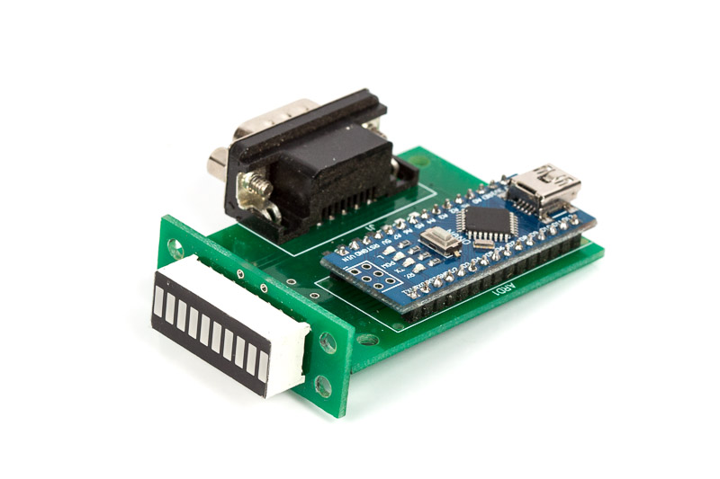
The Angle of Attack display unit complements the main EFIS Display unit and works as an I2C slave to the main Display.
The main reason for showing AoA information on a separate display is that I want the display to be high up on the instrument panel and to be very prominent and colour coded.
The angle of attack information is sourced from Module-A and transmitted to the CAN-Bus network. EFIS Display module converts it into I2C massages and sends it to the LED Bar-graph display.
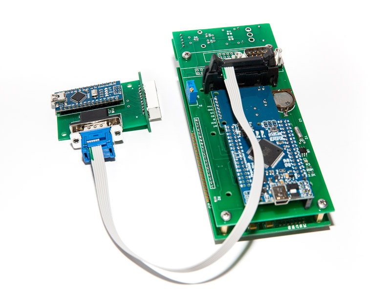
The AoA Display connected to the display unit via ribbon cable using the first 5 pins of the extension connector on the Display Unit. The connection supplies power and 2-wire I2C connectivity (SCL and SDA signals)
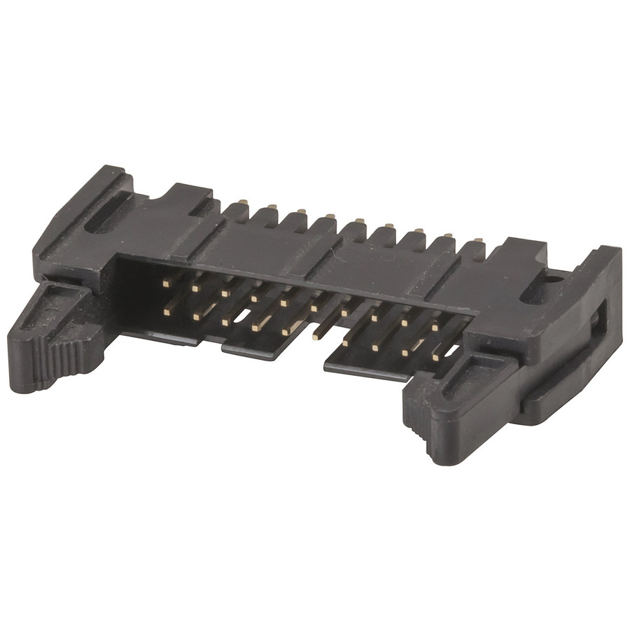
Use locking 20-pin IDC connector on the Display Unit side.
Connectors pinout (both IDC and D-Sub)
- Ground
- Power +5v
- Power +3.3v (not used)
- SCL
- SDA
You can find more information about the Angle of Attack on the page for Standalone AoA Display
Parts list:
| Schematics Reference | Part Name |
 Arduino Nano Arduino Nano | |
 LED Display PCB Board LED Display PCB Board | |
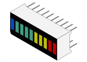 LED Bar-graph KYX-B10BBGYR LED Bar-graph KYX-B10BBGYR | |
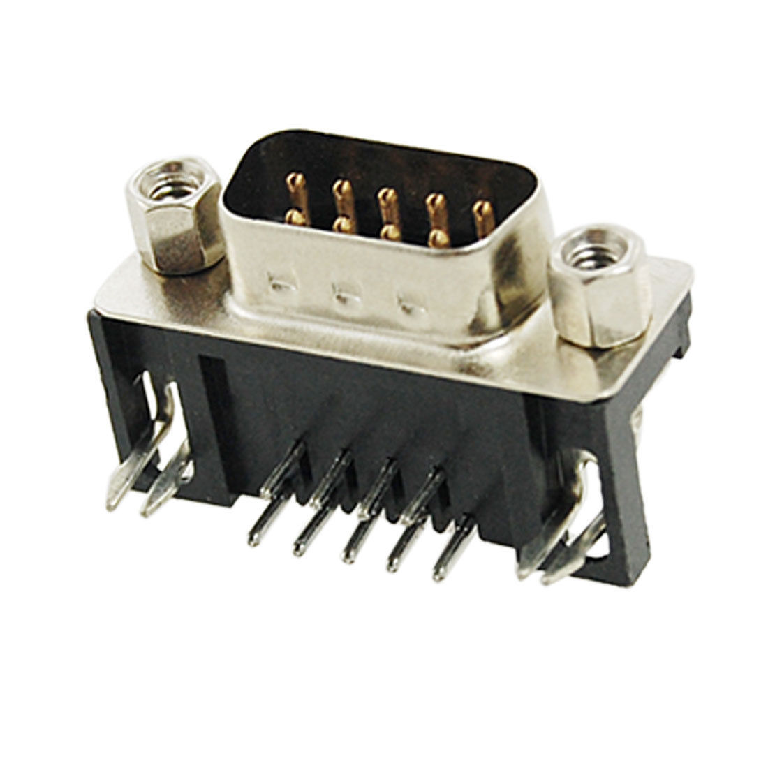 9-Pin D-SUB Male Right Angle connector 9-Pin D-SUB Male Right Angle connector |
Assembly Instructions
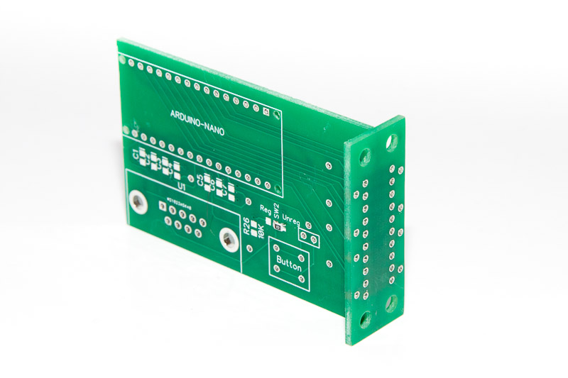
While assembling the unit please be careful not to break-off the T-connected PCB boards.
| Step | Instructions |
| 1 |  Solder the LED Bar-graph KYX-B10BBGYR. Make sure orientation is correct. Red LEDs at the top, Blue at the bottom with PCB board oriented with D-SUB connector pointing down. Solder the LED Bar-graph KYX-B10BBGYR. Make sure orientation is correct. Red LEDs at the top, Blue at the bottom with PCB board oriented with D-SUB connector pointing down. |
| 2 |  Prepare the two 15-pin headers for Arduino Nano by shortening the longer side to the same size as the sorter side Prepare the two 15-pin headers for Arduino Nano by shortening the longer side to the same size as the sorter side |
| 3 | 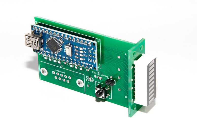 Position the Arduino Nano on the main board and solder all the pins on both sides Position the Arduino Nano on the main board and solder all the pins on both sides |
| 4 | 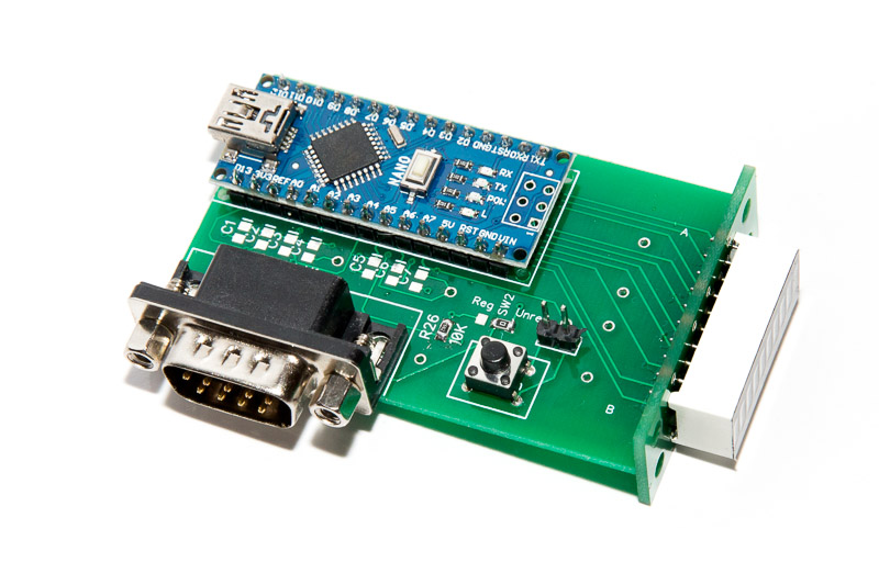 Position and solder the 9-pin male D-Sub connector Position and solder the 9-pin male D-Sub connector |
| 5 | 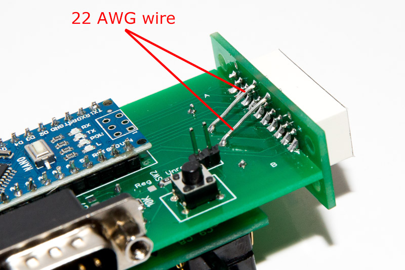 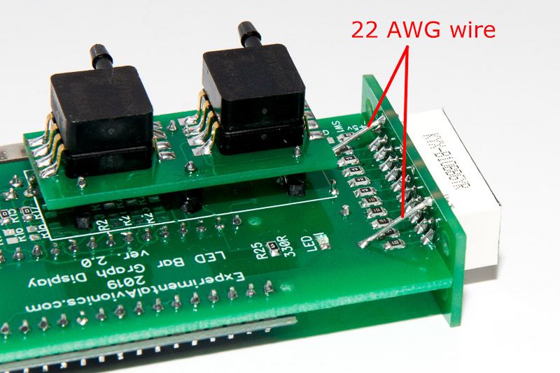 Optionally make reinforcing trusses by soldering 22 AWG wire in four places (see the pictures) Optionally make reinforcing trusses by soldering 22 AWG wire in four places (see the pictures) |
| 6 | Upload the software |
| 7 | Solder the 20-pin Male Locking IDC connector on the Display Unit board |
Download the software from GitHub: Not there yet
New to Arduino? –
- Go to YouTube
- Search for “upload program to arduino”
- Watch a couple of videos on how to load the software into Arduino Uno. The workflow for other Arduino boards (Mega, Nano, etc) is practically identical.
Uploading the software onto the Arduino Nano board
- Click on the link for software you want to download from my GitHub. https://github.com/ExperimentalAvionics/AOA_Display_EFIS
- Click on the “Clone or Download” button (Green button on the right hand side)
- Click “Download ZIP”. It will initiate the file download. The file name will be something like AOA_Display_EFIS-master.zip
- Unzip the downloaded file into the folder where all your other Arduino projects are. On Windows it will be something like c:\Users\<MyName>\Documents\Arduino\
- The unzipped folder name will look like c:\Users\<MyName>\Documents\Arduino\AOA_Display_EFIS-master. You need to rename it removing the “-master“.
So the folder name will look like this: c:\Users\<MyName>\Documents\Arduino\AOA_Display_EFIS\ - Start your Arduino IDE, navigate to the folder you have just created and open up the AOA_Display_EFIS.ino file. Note the name of the file to open is the same name as the name of the folder.
- Ensure the correct board is selected: Tools > Board > Arduino Nano
- Connect the Arduino board to your PC with a USB cable.
- Ensure the correct COM port selected: Tools > Port
- Press the “Upload” button.
- Wait for the code to be uploaded onto the Arduino board. Watch for the error messages at the bottom.
ToDo/FixIt
| # | Description |
| 1 | |
| 2 | |
| 3 | |
| 4 |