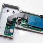
EFIS 19264
[symple_box color=”red” fade_in=”false” float=”center” text_align=”left” width=”100″]This page is Archived. Its content might be expired or not relevant.[/symple_box]
Overview
The idea is to build a backup (or primary?) EFIS for a light experimental aircraft for for a fraction of the cost of functionally similar Dynon, GRT or Garmin unit. It turns out that it is not as hard as it might seem.
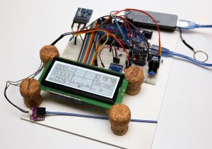
The EFIS includes ASI, ALT, VSI, Magnetic compass, Slip indicator (Ball), Attitude indicator (artificial horizon), Flight-time timer, UTC/Local time and G-meter.
QNH and other instrument settings are done via “push-turn” knob (encoder), just like on Dynon or Garmin EFIS.
Version 1.1 includes flight parameters recorder (a sort of black box) on an SD card.
Design
- CPU Board
The system built around Arduino Mega 2560 board. At this stage, I’m using a non-genuine 12MHz model. It works just as well as the genuine 16Mhz model but it’s a lot cheaper. I think any other Arduino board would be suitable for the project.
The board has on-board voltage regulators to supply power for itself and other components, both 5v and 3.3v. The input power could be in the range of 6 and 20v. With a 9v power supply, the system consumes around 125mA. - Display
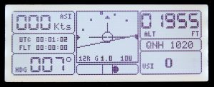
EFIS display layout When I started I was thinking of using a colour display. As it turns out, good sunlight-readable colour displays are very expensive and require significant processing resources. So, after some research I settled on a 4″ 192×64 pix KS0107/KS0108 based monochrome display from BuyDisplay for $23 USD delivered. The display has a nice white back-light and looks fantastic under direct sunlight. The display has a resolution of 192×64 pixels and is about 4″ diagonal. It is big enough to display all important flight information.
- Gyro
For gyro I chose a new BNO-055 sensor from Bosh. It seems to be superior to other popular solid state gyros, mainly because it has internal processor calculating Euler vectors including magnetic heading. It is quite expensive though, and it’s most expensive component of the EFIS (so far). - Altimeter
I tested BMP-085, BMP-185, BMP-285 and MS5611 sensors and found that MS5611 (aka GY-63) is quite a bit better than the BMP-x85 series. The problem with all these sensors is that they are mounted on the PCB board. There is no nipple to attach a plastic tube to them. I had to build an air-tight enclosure for them so it could be connected to the static port of the airplane. I have built one and it is okayish for testing the system, but I think I’ll have to replace it with some other factory-built sensor that has a nipple. I’m currently testing HSCDANN001BA2A3 on a separate Arduino board. - Airspeed sensor
I used a MPXV5010DP analog differential pressure sensor that should be good for airspeeds up to about 250kn. For slower (below 112kn) aircrafts the MPXV7002DP sensor can be used – it is a bit cheaper.
I will probably replace the analog sensor with the digital one (I2C), something like Honeywell HSCDDRD001PD2A3 or MS4525DO-DS5AI001DP It might add about $40 to the total cost of the project. - Clock
A board with a DS3231 chip and a rather large replaceable CR2032 battery used as a real-time clock. The battery should last for 2-3 years.
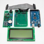
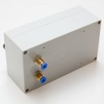
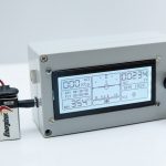
All the components mentioned above come attached to their PCB boards with all the required circuity. So all that needs to be done to get the device going is to attach these boards together and upload the software.
While testing the design, I used a simple evaluation board. Once the design is stable I’ll make a proper PCB board interconnecting all these tiny sensor boards.
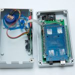
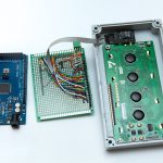
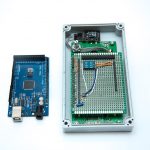
Jamming all of this stuff into the plastic case is the biggest challenge. The display is attached to a large PCB, so the case looks a bit too large for the size of the screen. Anyway, it all fits into the case nicely and it’s ready for testing… at zero ft AGL on top of my car’s dashboard.
Test plan:
- Airspeed accuracy.
- Altitude accuracy
- Magnetic compass.
- Hot conditions.
- Effects of vibration.
- Artificial horizon accuracy (will not try inverted flight in the car 🙂 )
Schematics and software downloads
Credits
My display layout to a great degree is based on the Marc Robitaille prototype of the very similar EFIS. Thank you Marc!
I’m very grateful to many people who put up various instructional videos on YouTube (Dejan Nedelkovski,..).
I also would like to say thank you to good people from Adafruit whose libraries I use in my projects. If you are in the US, I encourage you to buy some stuff from them to support their great work.
