EFIS 19264 Ver 1.2
[symple_box color=”red” fade_in=”false” float=”center” text_align=”left” width=”100″]This page is Archived. Its content might be expired or not relevant.[/symple_box]
Schematics, parts list and software download
[symple_box color=”red” fade_in=”false” float=”center” text_align=”left” width=”100%”]This version of the EFIS is no longer supported or developed further.
Please see the pages related to EFIS version 2 and above.[/symple_box]
 Version 1.2 is very similar to 1.0.
The main differences are:
- Flight Data Recorder (has some stability issues in this version)
- Honeywell static pressure sensor instead of the MS5611
- Adadfruit BNO055 gyro instead of Atmel
- Proper PCB boards instead of prototype boards
- Angle of attack sensor
- Optional voltage regulator
- Connector for external I2C devices (expansion port)
Flight data recorder registers various parameters from all the sensors onto SD card at regular pre-configured intervals. (every 1 second for example)
The data stored in comma-delimited files and can be analysed later via MS Excel.
Testing progress
See Testing category in my Blog
Schematics
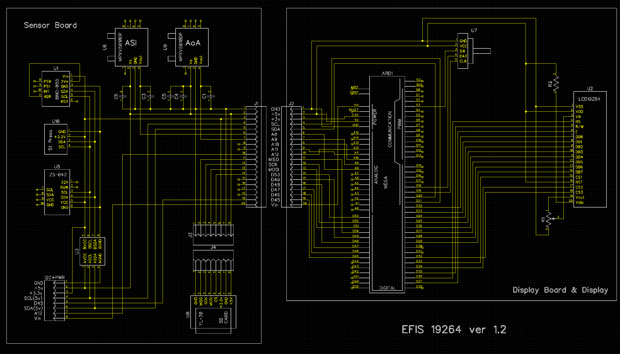
I recommend to open the image in a new tab or save the file on your disk.
Software Download
Download from Google Drive
Although the software is very similar to ver 1.0 I need to cater for vertical orientation of the BNO 055 board, new pressure sensor and implement a few other ideas that people gave me since original design was published.
Please note, this is not the final version of the software. I’m still working on it. I publish it for people to have built the hardware and need a starting point with the software.
Update 28/Nov/2016: Added missing library files for BNO-055
Parts list:
| Schematics Reference |
Part Name |
| U2 | Display 4″ 192×64 pix KS0107/KS0108 based monochrome display from BuyDisplay |
| ARD1 | Arduino Mega 2560, non-genuine model (it is cheaper, works as good). |
| U1 | Adafruit BNO055 9 axis absolute orientation sensor board. |
| U7 | Rotary Encoder KY-040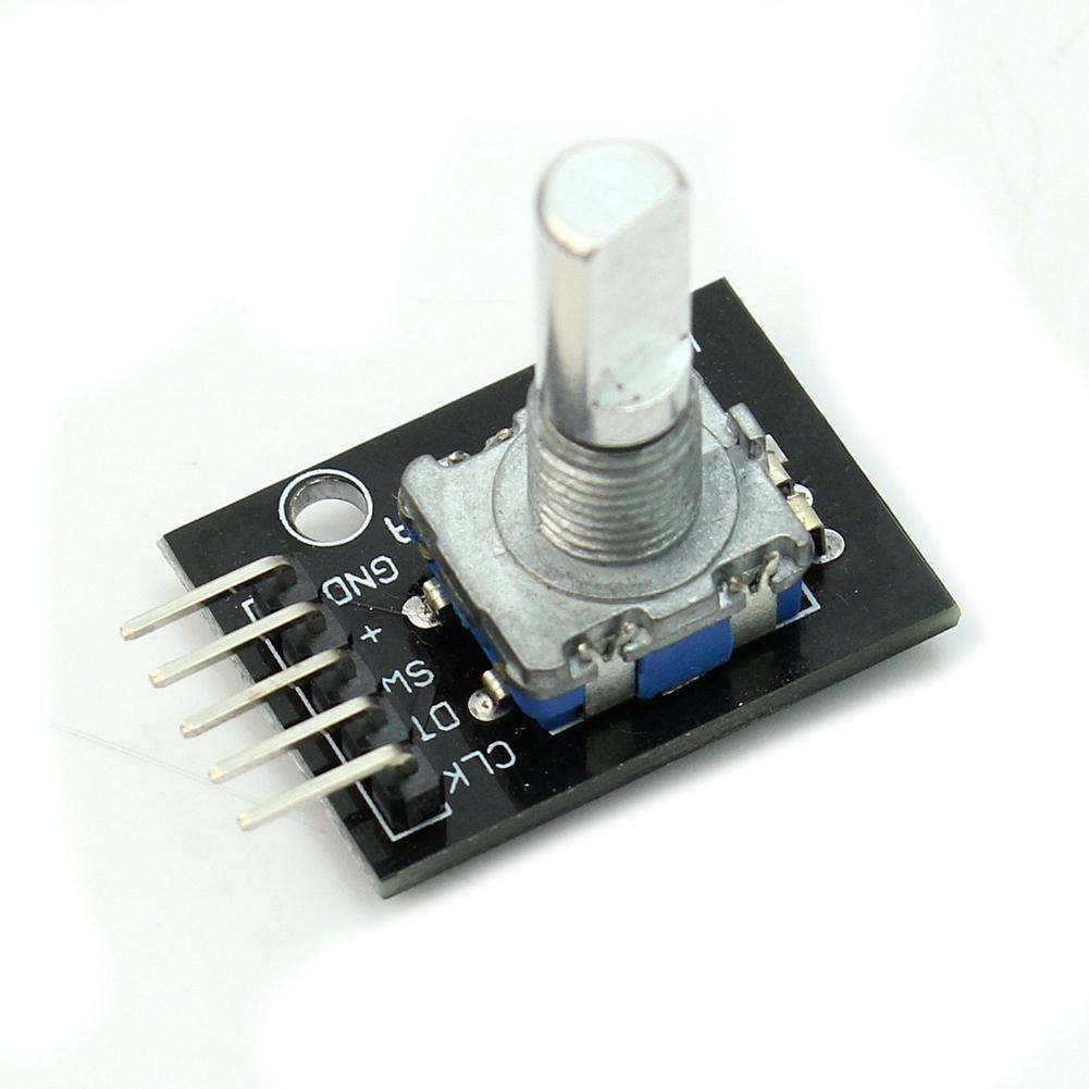 |
| U6 | Differential pressure sensor MPXV5010DP |
| U4 | Honeywell static pressure sensor HSCDANN001BA2A3 (or HSCDANN015PA2A3). |
| U5 | Real time clock DS3231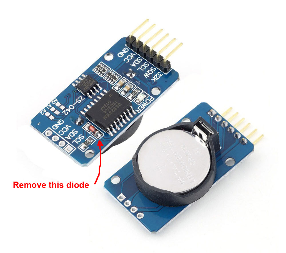 |
| U3 | Level shifter 3v/5v |
| R1 | 10K potentiometer |
| R2 | 69 Ohm resistor |
Pneumatic fittings (x2) and tubing (pitot and static) |
|
| Plastic case |
User manual:
Design and assembly instructions

In order to continue development and testing of the EFIS I’ve decided to walk away from prototype boards and create a proper PCB boards for the Display Board and Sensor Board. At the same time I’d like to stick to the idea of using pre-assembled miniboards such as Adafruit BNO055 board, I2C levels shifter board, real-time clock etc. It allows to keep the cost of the system very low and makes the assembly relatively simple.
[symple_box color=”gray” fade_in=”false” float=”center” text_align=”left” width=””]I have a few spare PCB boards for Display and Sensor boards available.
Please visit our online store to purchase the boards.
Please note: these are just PCB boards, with no components soldered to them. You will need to buy the components from other sources like Mouser.com, Digikey.com, eBay, etc.
[/symple_box]
[symple_divider style=”solid” margin_top=”20″ margin_bottom=”20″]
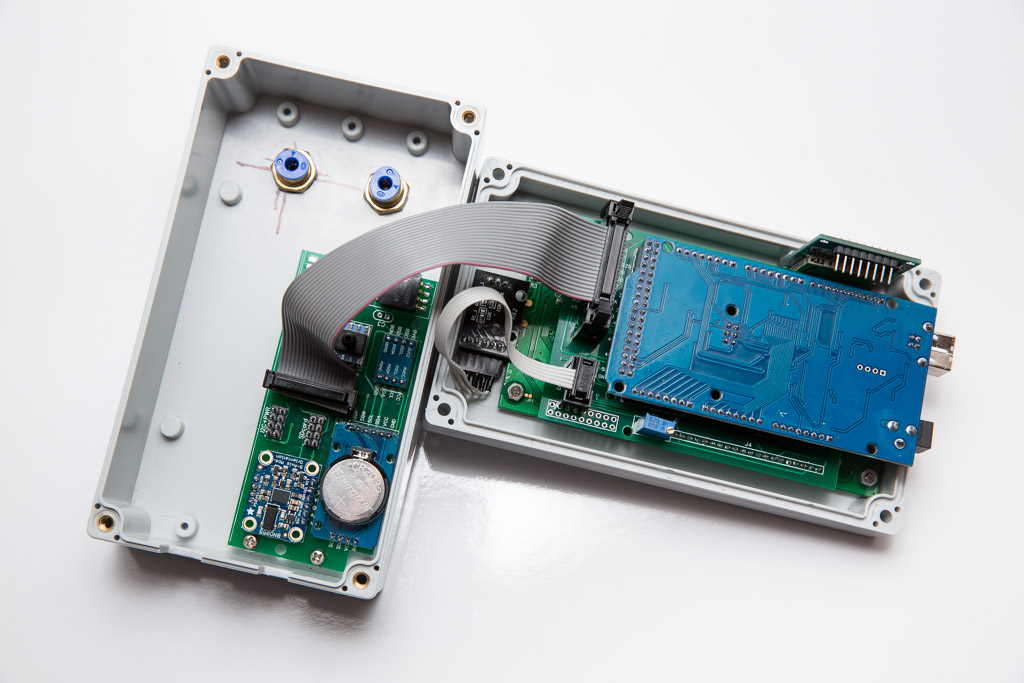
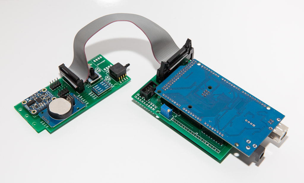
There are two PCB boards
- Display Board. It’s purpose to connect Arduino board to LCD display and provide “standards” way to talk to sensor board. So it is like a building block suitable for other types of avionics. For instance, in parallel to the EFIS I’m working on Engine Management System (EMS) that will be using exactly the same LCD display, same Arduino Mega board and the same Display Board. Only the sensor board will be different.
- Sensor Board. It takes care of all the relevant sensors and connects to the Display Board via 20-wire IDC connector. The idea is to make the sensor board independent of the processor platform. If later down the track I decide to use Pyboard instead of Arduino, I can use the same Sensor Board.
[symple_divider style=”solid” margin_top=”20″ margin_bottom=”20″]

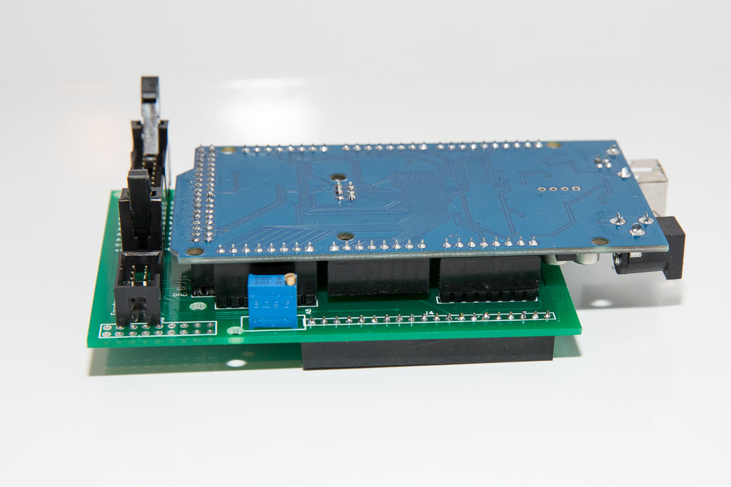
Display Board is very simple and does not have many components – just one 69 ohm resistor and one 10k trim pot to adjust LCD contrast. It has a lot of male header pins to connect to Arduino board and two IDC male connectors for Sensor Board cable and Encoder cable. Header pins can be used instead of IDC connectors. If you go this path you can save a few bucks but be mindful of the cable orientation when you connect things together. The pictures on the page show very fancy 20 pin IDC connector on the Display Board but on the Sensor Board the cable connects to a simple set of header pins. This is OK as it is practically impossible to connect the ribbon cable incorrectly to the Sensor board if it is connected properly at the Display Board.
On the bottom side of the Display Board there is a line of female headers to connect to the LCD Display.
Orientation of the trim pot is not important. You don’t have to use multi-turn trim pot either. Any 10k trim pot with standard 2.54mm legs spacing will do the job.
[symple_divider style=”solid” margin_top=”20″ margin_bottom=”20″]
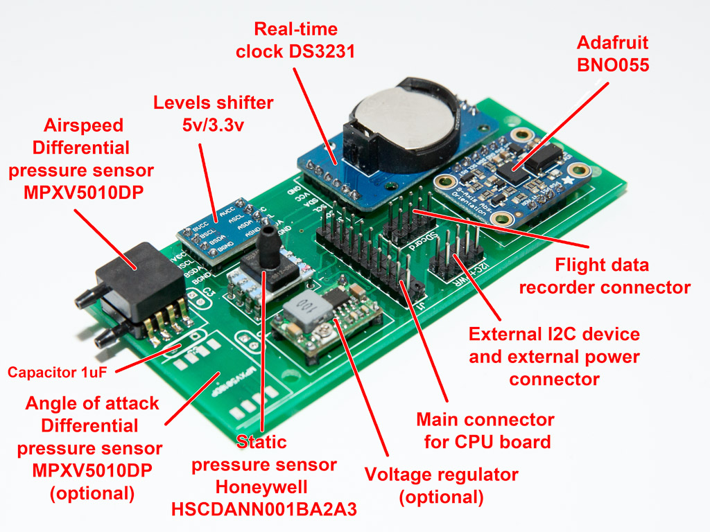
Sensor Board unites all the sensors together on one PCB board providing “standard” interface to the main CPU board. Almost all components on the Sensor Board are pre-assembled mini-boards soldered to the PCB using shortened male headers. It makes the assembly of the board very simple.
Here is a few notes on the components used for this Sensor Board:
– Voltage regulator. Optional. It allows to power the system through the Sensor Board via one of the pins on the “External I2C” connector. You might need it if you have quite unstable voltage in your plane or it often goes above 16v. You dont need it if you plan to power the EFIS via USB or Arduino’s barrel power connector. If you dont want to install this voltage regulator, simply connect “In+” and “Out+” terminals on the PCB.
If you DO want to have it but plan to use Arduino’s power connectors while testing the system (USB or barrel), you need to pull out one corner pin from the 20-pin connector. See pictures. You will need to install the pin back if you plan to power your system through the Sensor Board.
– Angle of Attack sensor. Optional. AoA works exactly the same way as on Dynon systems. In fact I’m going to use their pitot probe. The sensor measures pressure difference between the normal pitot, parallel with the wings chord, and the one that angled 30 degrees down. It is pretty straight forward. The plan is to use separate device to display the AOA and provide aural warning. Most likely it will a line of LEDs connected to the sensor board via I2C port. At this stage, the software for it is not ready.
AoA sensor is wired to A9 pin on Arduino Mega.
– Level shifter for I2C is not required if you decide to go with some other CPU board that works with 3.3v levels – such as Teensy, Pyboard, etc. In this case simply connect ASDA to BSDA and ASCL to BSCL.
[symple_divider style=”dashed” margin_top=”10″ margin_bottom=”10″]
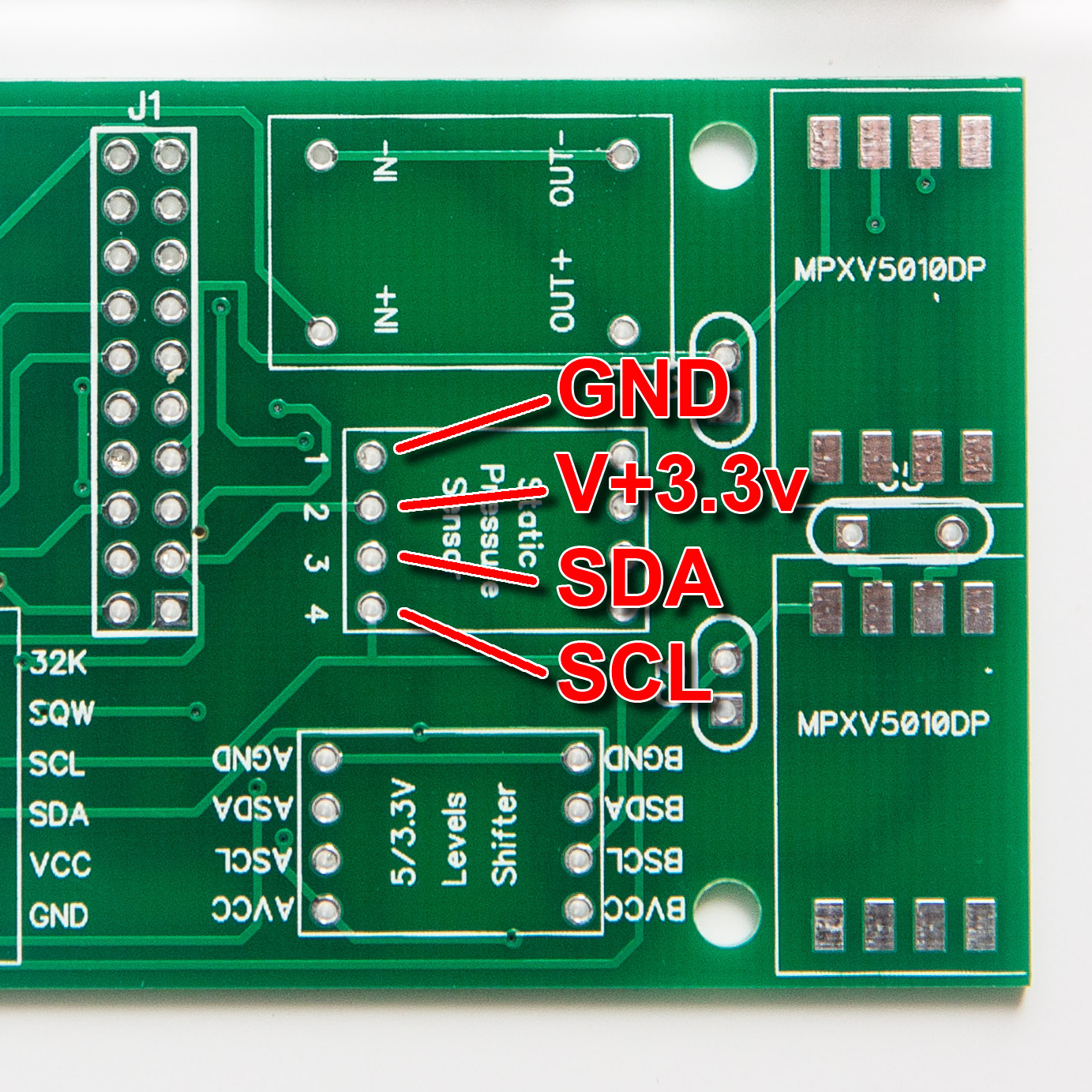 – Static pressure sensor. I’ve been experimenting with building airtight enclosure for cheap pressure sensors and could not achieve a result that would satisfy me from reliability point of view. So I decided to go with expensive Honeywell static pressure sensors. Anyway, if you are happy to use open static pressure sensors (like BMP180) or you are successful with building a reliable enclosure for them, you can simply connect your sensor in place of the Honeywell – it is just another I2C device. (You will need to adjust software to work with your sensor).
[symple_divider style=”dashed” margin_top=”10″ margin_bottom=”10″]
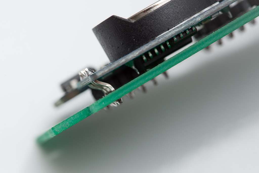 – Real-Time Clock (RTC). It seems like there are at least two slightly different boards on the market for DS3231 RTC – one is slightly shorter than another. So depending of which one you’ve got you might need to S-bend the header pins on the EEPROM side of the board to solder the RTC board to the Sensor Board’s PCB. (See the picture) Note: EEPROM part of the RCT is not being used. Its pins used just to hold boards together.
[symple_divider style=”dashed” margin_top=”10″ margin_bottom=”10″]
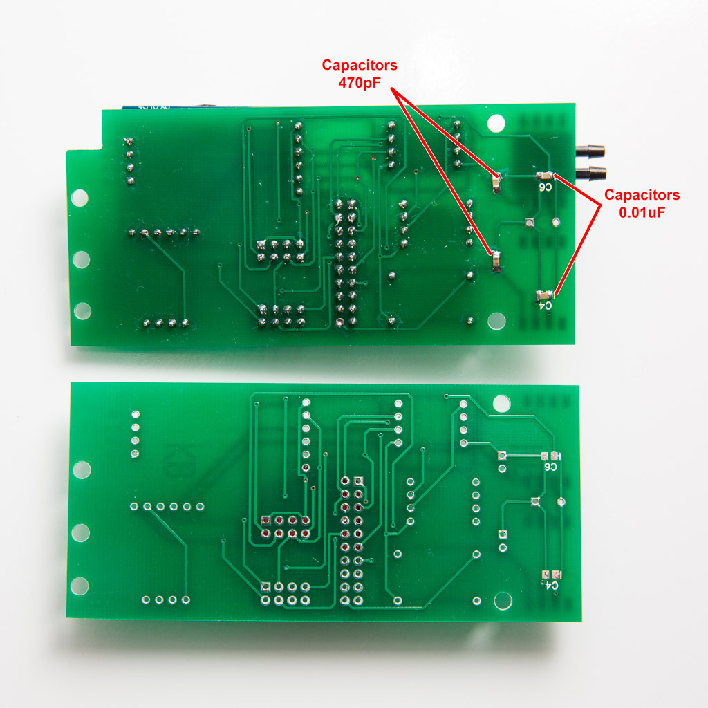
– Capacitors around differential pressure sensors. These capacitors required for power decoupling and signal filtering. So strictly speaking you dont need them to power up the system and see if it works, but be sure you have them when you will be verifying the airspeed numbers. There are two 0.01 uF SMD capacitors on the bottom side of the Sensor Board. These could be a bit challenging to solder due to small size. Other capacitors are regular ceramic through-hole capacitors. Note that images show two 470 pF SMD capacitors soldered to the hole pads. This is because I dint have the normal capacitor at the time, but had some spare SMDs. It is up to you which type you want to use.
[symple_divider style=”dashed” margin_top=”10″ margin_bottom=”10″]
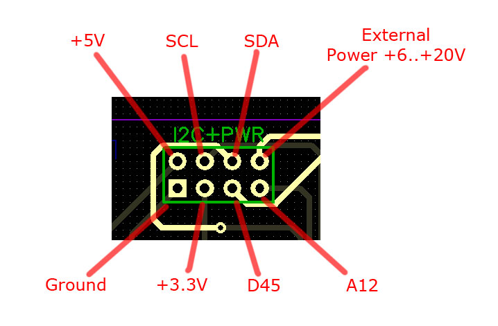
Here is the main connector pinout (IDC-20) 
[symple_divider style=”dashed” margin_top=”10″ margin_bottom=”10″]
(To be continued)