Backup Power

Status: In operations
Night VFR certification requires backup power source for some instruments.
In order to comply with the requirement the CAN HUB board has been modified to accommodate additional battery charge circuit.
With three 3000mAh 18650 batteries the unit provides 2 hours of power (about 30W*Hrs) to all avionics onboard excluding radios and the transponder.
Backup Battery Charge Controller
Essentially CAH_HUB ver 3 is the same as CAN _HUB ver 2 with a battery charge controller between the switch-mode power converter and the input power.
Charge controller is based on MP26123 chip from Monolithic Power (MP26123 Datasheet). It is reasonably priced, readily available and provides sufficient control over safe charging for three 18650 Lithium-Ion batteries.
Key features and controls:
- The unit is configured to charge at initial current not above 1.3 A (R3=150 mOhm).
- Charging process will stop if the battery temperature goes outside of a safe range (0C – 50C).
- Charging will also stop if it runs for more than 3 hours (indication of faulty battery).
- Fully discharged battery will be trickle-charged with charge current of about 130mA until the batteries reach level of 3V per element.
- The unit has 4 output ports for monitoring the charger and the battery status. The ports are monitored by Module-A (see Module-A page for details).
Connecting the CAN HUB unit to the rest of the aircraft electric circuit.
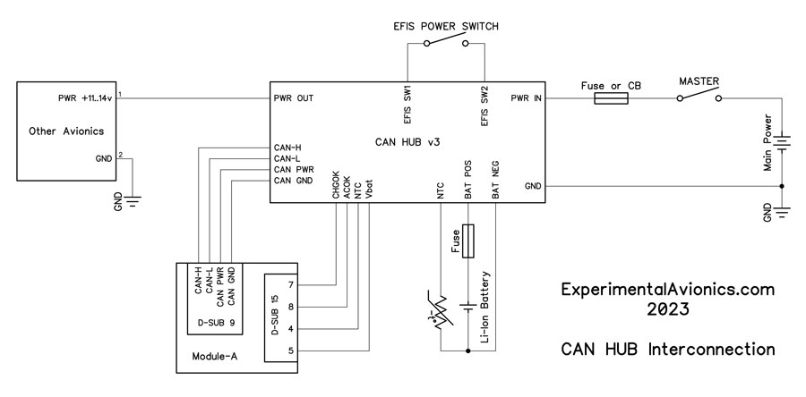
Same image in PDF format: CAN_HUB_3_Interconnection.pdf
Battery Unit
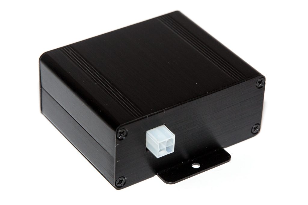
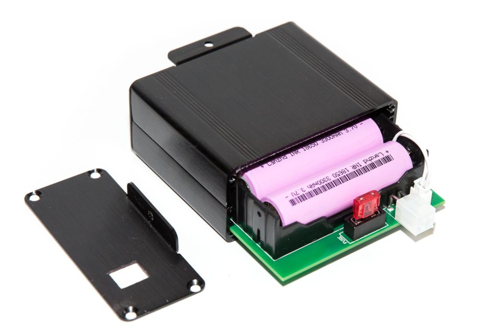
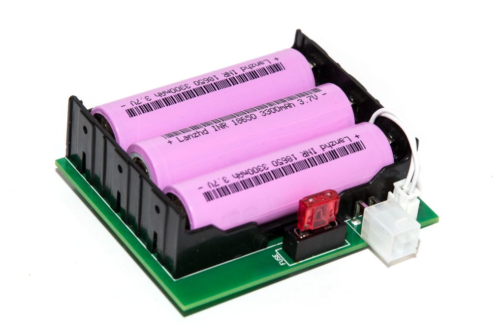
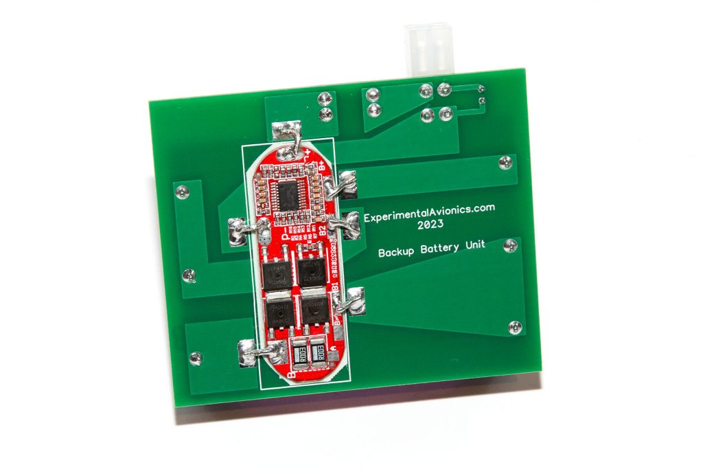
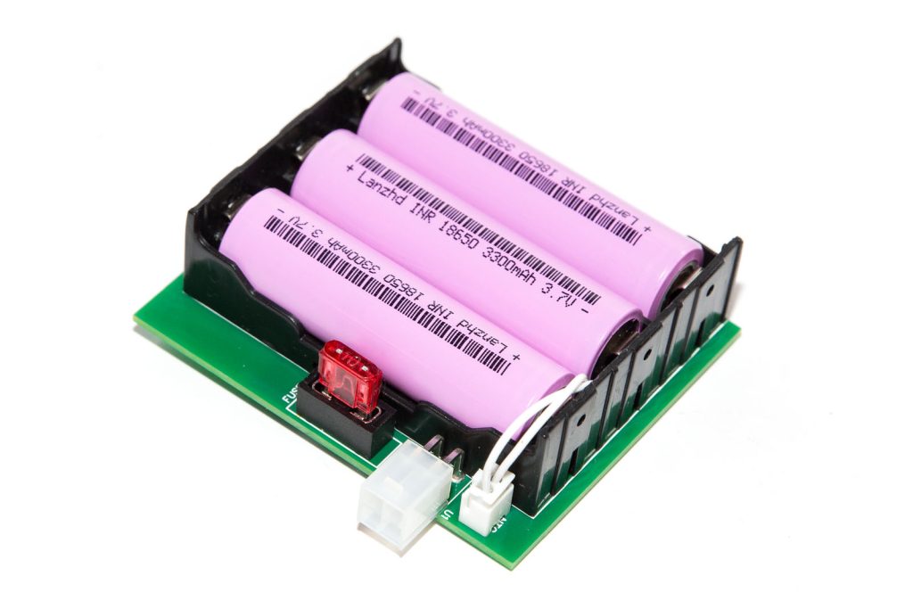
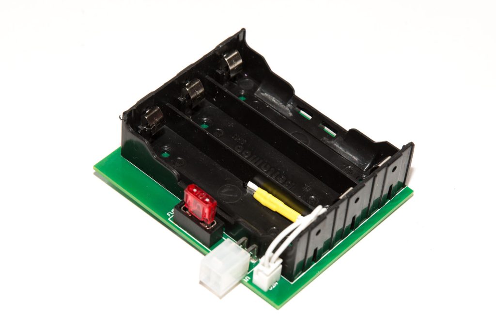
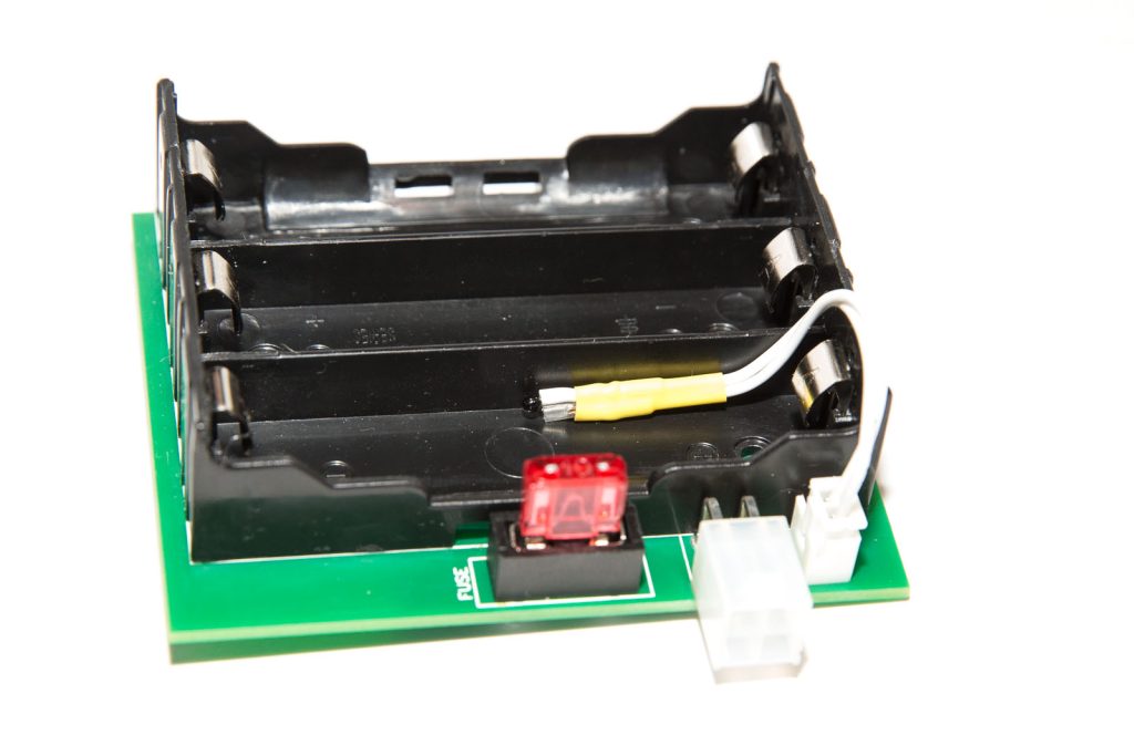
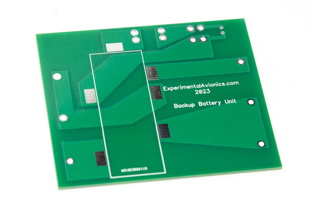
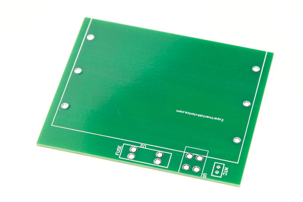
Parts list:
(being updated)
| Schematics Reference | Part Name |
| CAN HUB and Charge Controller | |
| CAN-HUB PCB Board (ver 3) | |
 Adjustable Voltage regulator Adjustable Voltage regulator | |
| Pin Molex Mini-Fit Jr connectors pair | |
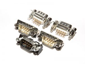 9-Pin D-SUB Male straight connectors, 5 pcs 9-Pin D-SUB Male straight connectors, 5 pcs | |
| Electrolytic capacitor 10-50 uF x 16v – Optional
Note: Do not install while the system is being tested. When individual units are powered via USB while connected to CAN HUB board, short reverse current into the discharged capacitor can damage the voltage regulator on Arduino Nano board. | |
| Battery Unit | |
Battery Unit circuit board | |
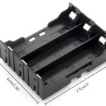 3-cell battery holder 3-cell battery holder
Source: Ebay or Aliexpress. One of the stores selling these holders: https://www.aliexpress.com/item/1005001861065786.htm | |
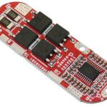 3S BMS board 3S BMS board
Source: Ebay or Aliexpress. One of the stores selling these BMS units: https://www.aliexpress.com/item/1005003346799285.html | |
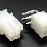 4 pin Molex 5569 connector 4 pin Molex 5569 connector
Source: RS-Online, Digikey, Aliexpress. One of the stores selling these connectors: https://www.aliexpress.com/item/4000821787946.html | |
| 2 pin JST connector | |
| Fuse holder with a 5Amp fuse. | |
| 10K Thermistor (NTC) | |
| 3 x Li-Ion 18650 batteries | |
| Aluminium Enclosure 88 x 38 x 100mm (Split Box)
Source: Ebay or Aliexpress. One of the stores selling these enclosures: https://www.aliexpress.com/item/1005004306861391.html | |
Assembly instructions
Coming soon
Software is not required for this unit
However, the unit integrates with Module-A for battery monitoring. Module-A’s software contains code to collect information from the charger controller and sent it into CAN-Bus.
Schematics & PCBs
CAN HUB and Charge controller Schematic PDF: Avionics_CAN_HUB_v3_Schematic
CAN HUB and Charge controller Schematic DipTrace (.zip): CAN_HUB_SCH_V30
CAN HUB and Charge controller PCB DipTrace file (.zip): CAN_HUB_v30_PCB_DipTrace
CAN HUB and Charge controller PCB Gerber file (.zip): CAN_HUB_v30_PCB_gerber
Backup Battery PCB Gerber (.zip): Battery_EFIS_rev1_gerber
Backup Battery PCB DipTrace (.zip): Battery_EFIS_rev1_diptrace
ToDo/FixIt
| # | Description |