Angle of Attack – Standalone unit
Updated: August 05, 2023
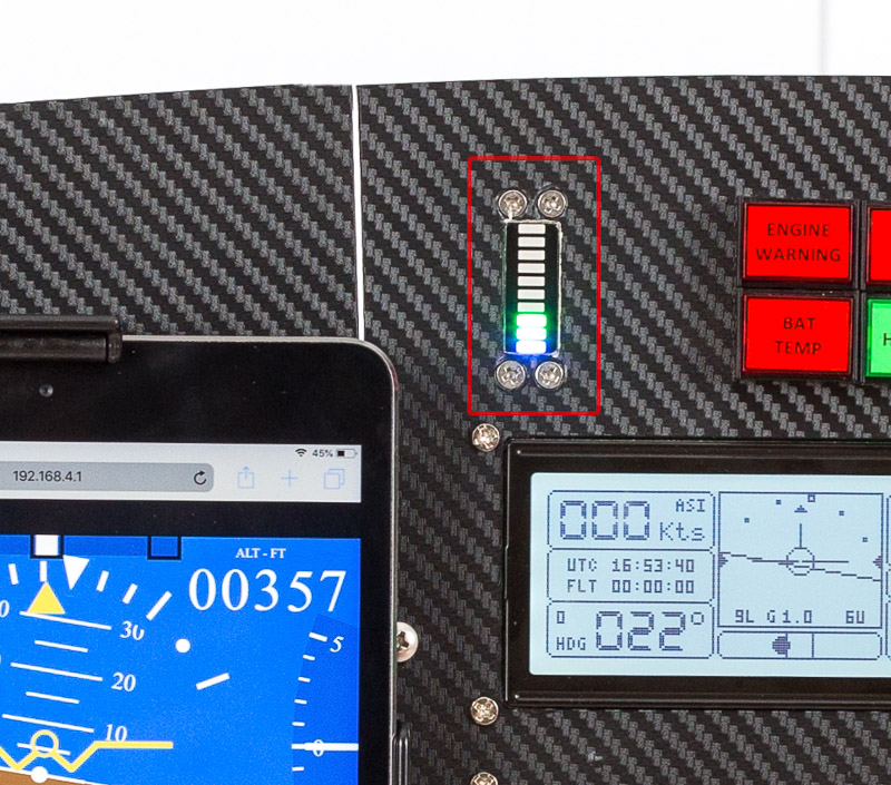
This is a standalone self-contained angle of attack indicator designed to be used in an experimental aircraft. This unit does not require the rest of the avionics set. All it needs to operate is power, and connection to the pitot, static and AoA ports.
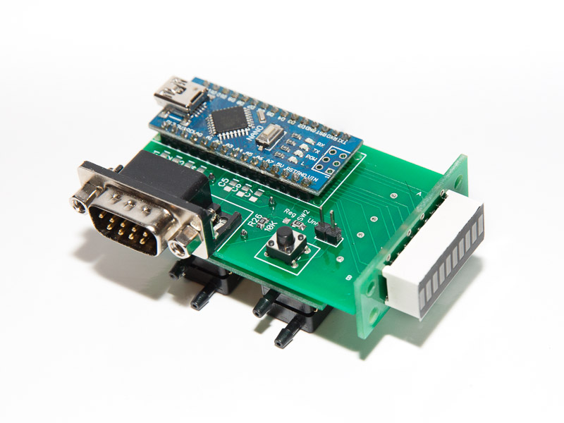
Just like most of the units in this project the Angle of Attack indicator is based on Arduino Nano and is very cheap and easy to build.
The indicator requires pitot tube that contains an additional port tilted 60 degrees off the main pitot port axis. The concept is very similar to the Dynon units. So Dynon’s AoA pitot tube can be used for this indicator. Another good option is a blade type pitot that is very common on Piper Cherokees. It requires a small modification – the hole at the back of the blade should be closed.
See the bottom of this page for AoA probe options.
The unit is in the testing phase. See the Blog
Your comments and contributions are highly appreciated.

How it works:
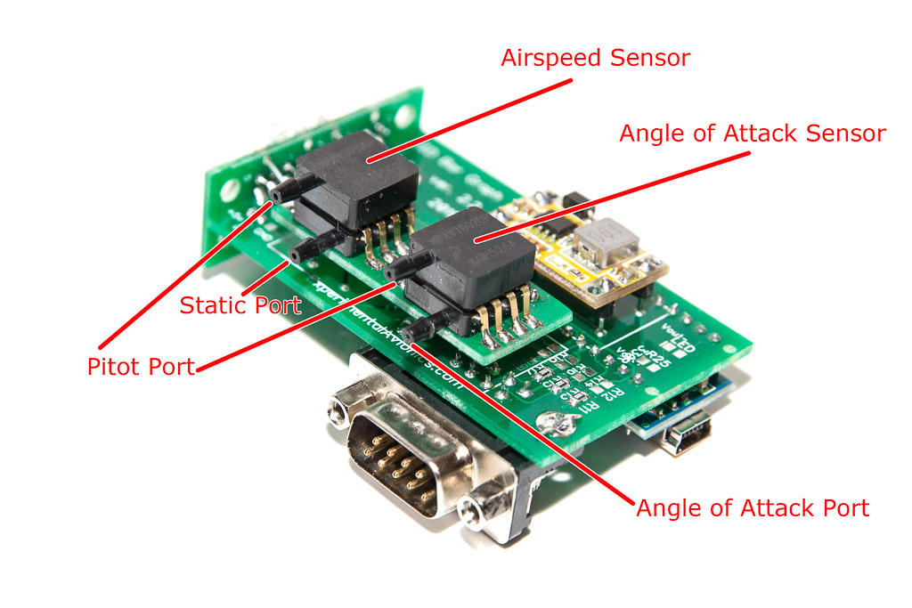
The unit measures differential pressure between Pitot port and AoA port (Paoa) as well as the differential pressure between Pitot port and Static port (Pias). The ratio of these two pressures (Pias/Paoa) is linearly correlated to Angle of Attack for a given flaps position. That’s it. It is that simple!
So, as you can guess, the unit needs to be calibrated for each flaps position. It also needs the flaps position information fed to the unit. Since we are dealing with a linear function, we need to obtain two values for each flaps configuration – one at stall angle and another at Zero lift.
Before the commencing the calibration ensure that you have correct values for Zero Lift AoA and Stall AoA hard-coded in the software.
To find these values for your airfoil use http://airfoiltools.com/search/index
For example for RV-12 airfoil (NACA 23012 or 23014 ???) the Stall AoA is 15deg and the Zero Lift is -1deg.
This NASA publication – https://ntrs.nasa.gov/archive/nasa/casi.ntrs.nasa.gov/19930091603.pdf – suggests that the Stall AoA is around 20 degrees.
Parts list:
| Schematics Reference | Part Name |
 Arduino Nano (Available in our store) Arduino Nano (Available in our store) | |
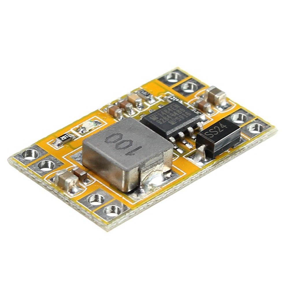 5V Voltage regulator (Step down Buck voltage converter)) (Available in our Store) 5V Voltage regulator (Step down Buck voltage converter)) (Available in our Store) | |
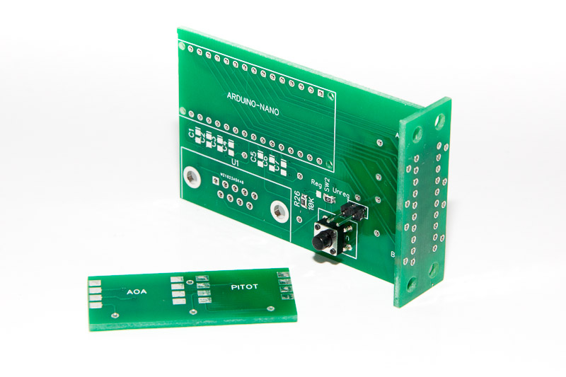 LED Display PCB Board (3 parts) (Available in our store) LED Display PCB Board (3 parts) (Available in our store) | |
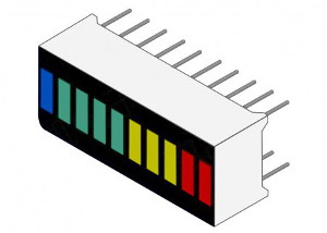 LED Bar-graph KYX-B10BBGYR (Available in our store) LED Bar-graph KYX-B10BBGYR (Available in our store) | |
 Airspeed differential pressure sensors [see below] (Available in our store) Airspeed differential pressure sensors [see below] (Available in our store)
| |
AoA differential pressure sensors [see below, 60deg AoA probe] (Available in our store)
| |
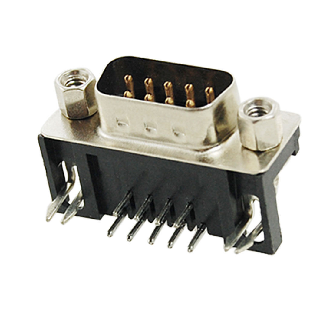 9-Pin D-SUB Male Right Angle connector (Available in our store) 9-Pin D-SUB Male Right Angle connector (Available in our store) |
Assembly Instructions
| Step | Instructions |
| 1 | 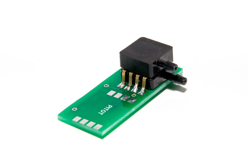 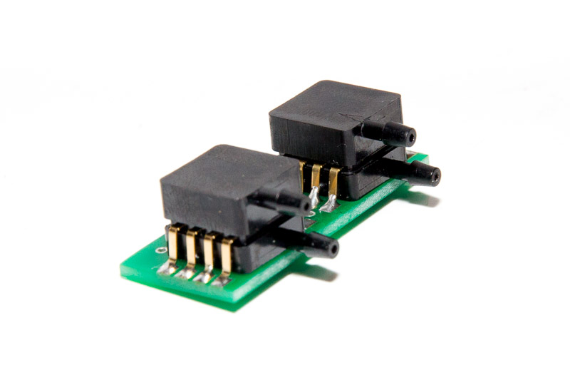 If it is not done yet, solder the pressure sensors on the sub-board. Make sure the positioning and orientation is correct. If it is not done yet, solder the pressure sensors on the sub-board. Make sure the positioning and orientation is correct. |
| 2 |  Solder the LED Bar-graph KYX-B10BBGYR. Make sure orientation is correct. Red LEDs at the top, blue at the bottom. Solder the LED Bar-graph KYX-B10BBGYR. Make sure orientation is correct. Red LEDs at the top, blue at the bottom. |
| 3 | 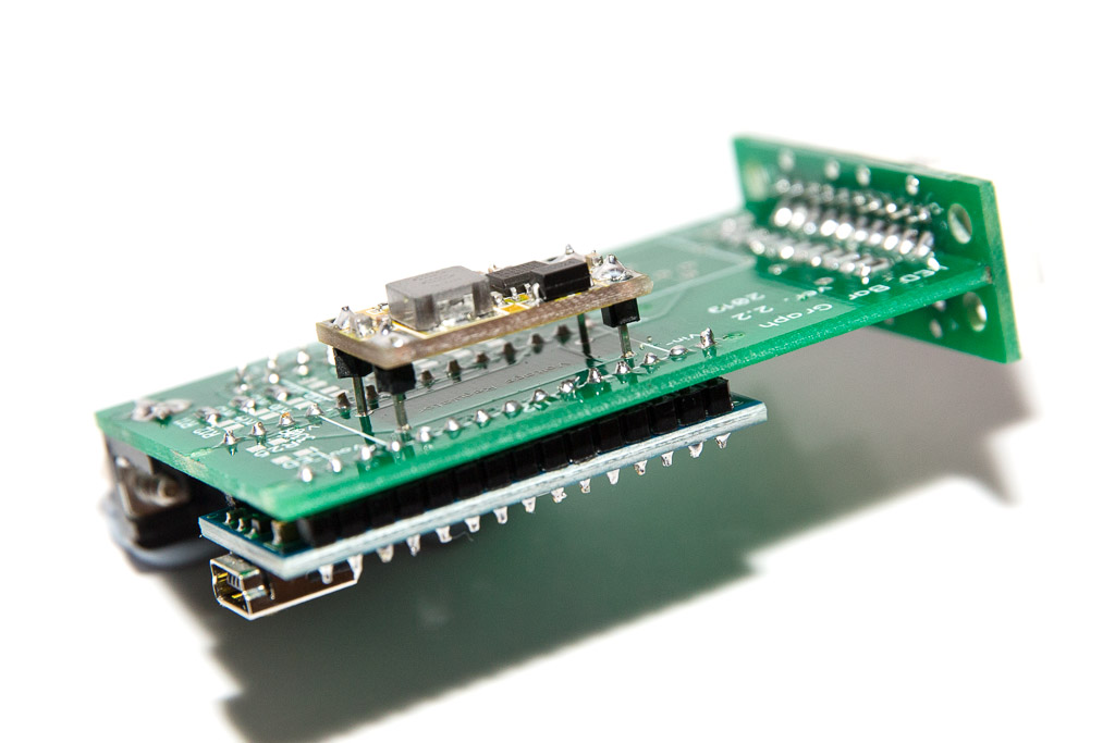 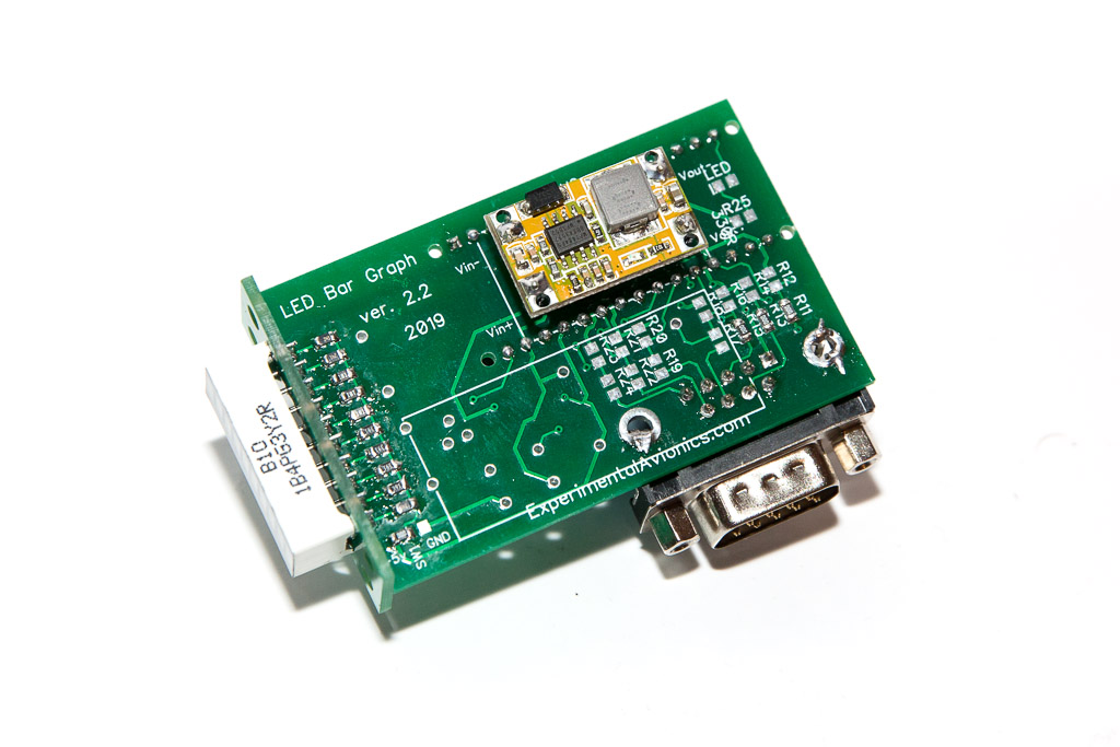 Break out 4 individual header pins and use them to solder the yellow voltage regulator board to the main board. Make sure to keep about 5-6mm off-set between the main board and the voltage regulator board. Break out 4 individual header pins and use them to solder the yellow voltage regulator board to the main board. Make sure to keep about 5-6mm off-set between the main board and the voltage regulator board.
Important! – make sure to complete this step before soldering the Arduino board (step 4) |
| 4 |  Prepare the two 15-pin headers for Arduino Nano by shortening the longer side to the same size as the shorter side. Prepare the two 15-pin headers for Arduino Nano by shortening the longer side to the same size as the shorter side. |
| 5 | 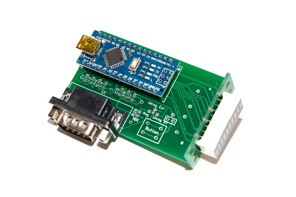 Position the Arduino Nano on the main board and solder all the pins on both sides. Position the Arduino Nano on the main board and solder all the pins on both sides. |
| 6 | 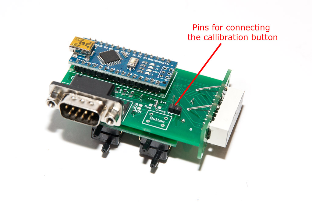 Position and solder the 9-pin male D-Sub connector as well as two pins for the calibration button. Position and solder the 9-pin male D-Sub connector as well as two pins for the calibration button. |
| 7 |   Make reinforcing trusses by soldering 22 AWG wire in four places (see the pictures) Make reinforcing trusses by soldering 22 AWG wire in four places (see the pictures)
Recommended technique: |
| 8 | 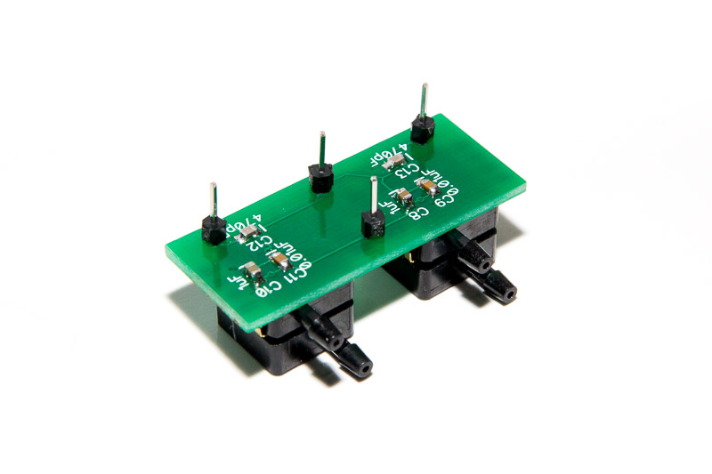 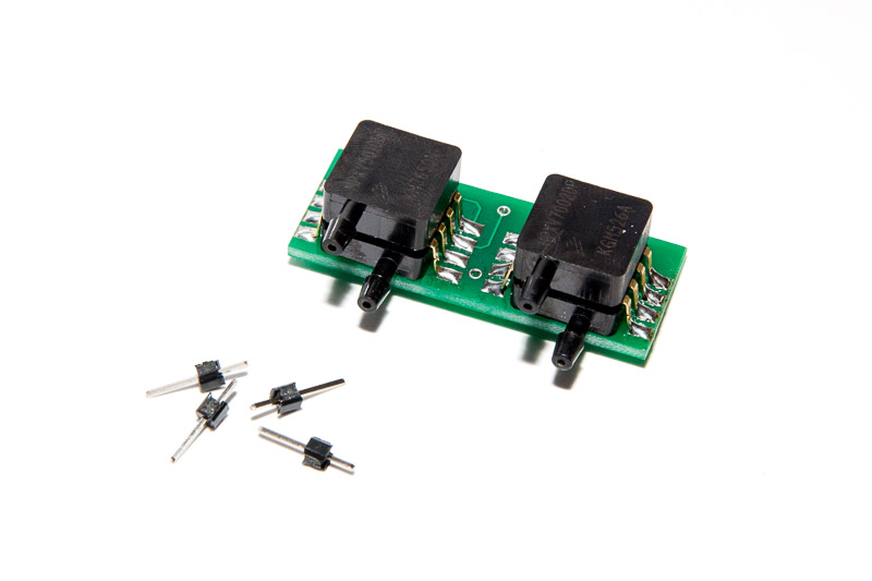 Separate four individual header pins and solder them to the pressure sensors sub-board Separate four individual header pins and solder them to the pressure sensors sub-board |
| 9 |  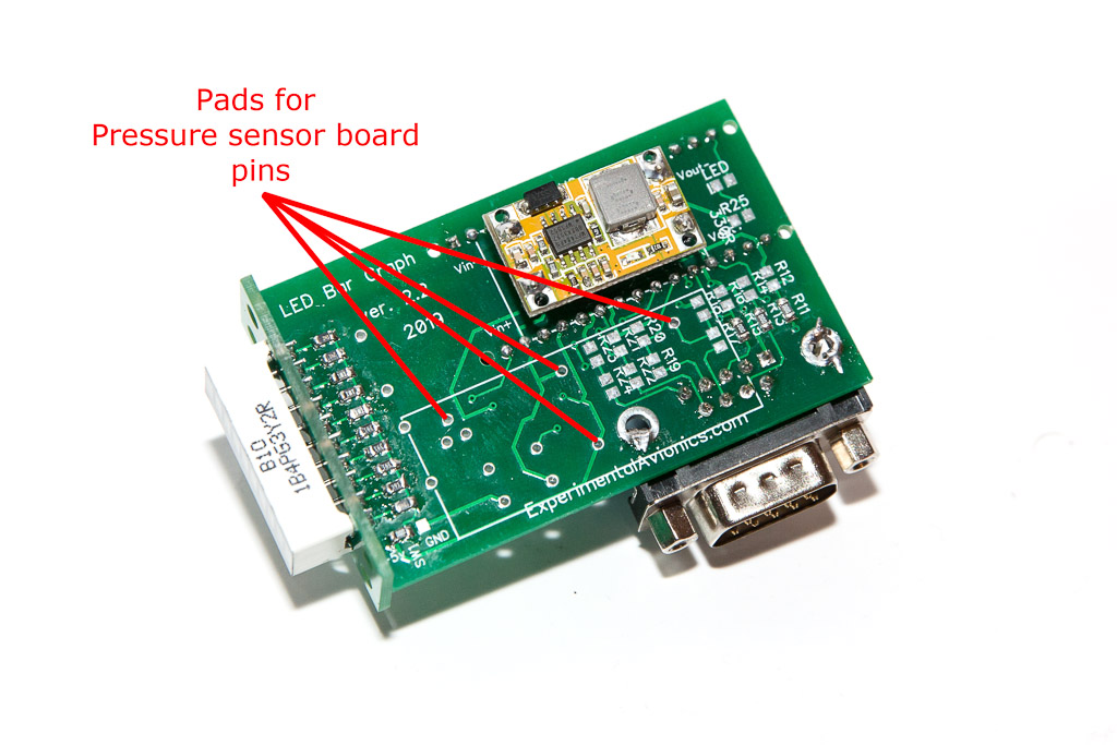 Position the sub-board on the main board and solder the 4 pins. Make sure the keep about 4-5mm off-set between the main board and the pressure sensor sub-board. Position the sub-board on the main board and solder the 4 pins. Make sure the keep about 4-5mm off-set between the main board and the pressure sensor sub-board. |
| 10 | Upload the software |
Some more details for those who assemble this unit from bare PCB boards or create the PCBs themselves
Resistors values for the LED bar graph
Blue and Red – 220 Ohm
Yellow – 150 Ohm
Green – 470 Ohm
Software
Download the software from GitHub: https://github.com/ExperimentalAvionics/AOA_Standalone
New to Arduino? –
- Go to YouTube
- Search for “upload program to arduino”
- Watch a couple of videos on how to load the software into Arduino Uno. The workflow for other Arduino boards (Mega, Nano, etc) is practically identical.
Uploading the software onto the Arduino Nano board
- Click on the link for software you want to download from my GitHub. https://github.com/ExperimentalAvionics/AOA_Standalone
- Click on the “Clone or Download” button (Green button on the right hand side)
- Click “Download ZIP”. It will initiate the file download. The file name will be something like AOA_Standalone-master.zip
- Unzip the downloaded file into the folder where all your other Arduino projects are. On Windows it will be something like c:\Users\<MyName>\Documents\Arduino\
- The unzipped folder name will look like c:\Users\<MyName>\Documents\Arduino\AOA_Standalone-master. You need to rename it removing the “-master“.
So the folder name will look like this: c:\Users\<MyName>\Documents\Arduino\AOA_Standalone\ - Start your Arduino IDE, navigate to the folder you have just created and open up the AOA_Standalone.ino file. Note the name of the file to open is the same name as the name of the folder.
- Ensure the correct board is selected: Tools > Board > Arduino Nano
- Connect the Arduino board to your PC with a USB cable.
- Ensure the correct COM port selected: Tools > Port
- Press the “Upload” button.
- Wait for the code to be uploaded onto the Arduino board. Watch for the error messages at the bottom.
Arduino Nano Bootloader issue
There are two types of Arduino Nano boards currently available on the market. They are the same from hardware standpoint but the Bootloader is different.
You might experience some difficulties uploading the code if the version of the board is incorrectly selected. Unfortunately there is no simple and reliable way to identify the version of the Bootloader.
If you have a problem uploading your code simply try to change the Bootloader version in your Arduino IDE:
Tools > Processor > ATmega328P
or
Tools > Processor > ATmega328P (Old Bootloader)
Schematics and PCB
AoA Schematic (PDF): Angle of Attack Schematics PDF
AoA PCB (Gerber): Bar_Graph2_AOA_rev2_gerber
AoA PCB (DipTrace): Bar_Graph2_AOA_rev2_DipTrace
ToDo/FixIt
| # | Description |
| 1 | Add the code for single-button in-flight calibration procedure and save the data in EEPROM |
| 2 | |
| 3 | |
| 4 |
AoA and Pitot probe options
 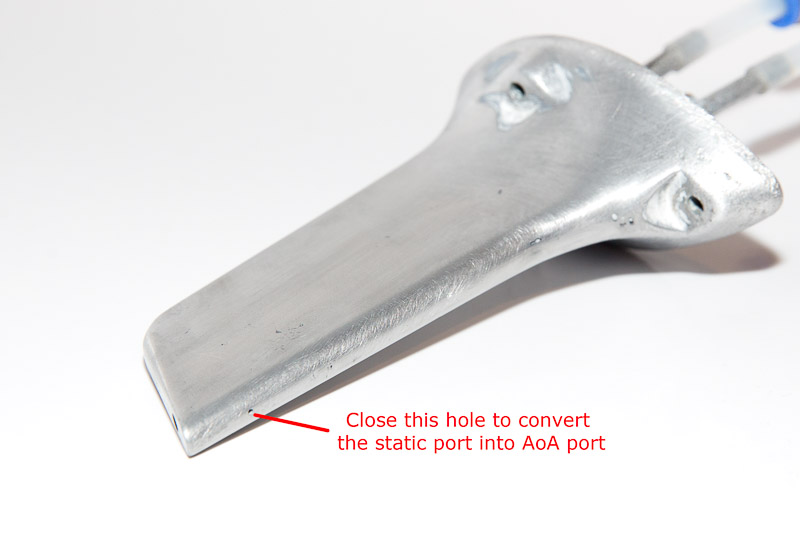 Piper Cherokee Pitot blade converted into AoA probe by closing the little hole at the back of the blade. Piper Cherokee Pitot blade converted into AoA probe by closing the little hole at the back of the blade.
|
 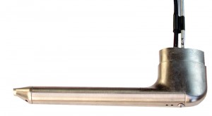 Dynon Pitot Probe Dynon Pitot Probe
|
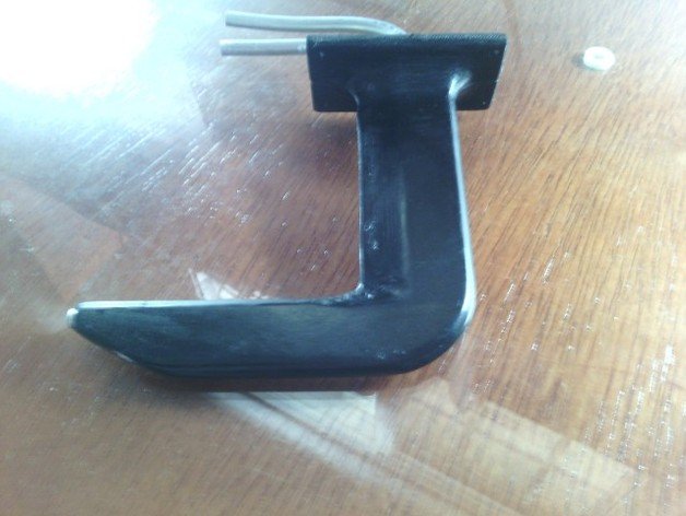 Similar to Dynon’s concept but 3-D printed Similar to Dynon’s concept but 3-D printed
|
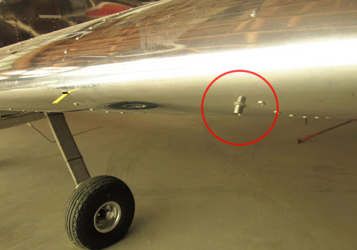 Rivet or football inflation needle on the leading edge. This really cheap and clever option. Rivet or football inflation needle on the leading edge. This really cheap and clever option.
|
Reference:
http://www.av8n.com/how/htm/aoa.html
http://www.nar-associates.com/technical-flying/angle_of_attack/DFRDAS_AccurateLowCostAoA.pdf