LED Lighting
Updated April 07, 2020
LED Strobes and Landing Lights
LED lighting has a lot of benefits over the traditional incandescent light and xenon flash.
Firstly, it is (of course) cheap. It is also very economical and conducive to DIY.
For my RV-12 I chose to build my own wingtip strobes and landing lights.
I don’t plan to do night flying, so positioning lighting (red, green and white) was out of scope for this project. All I want is to be visible in the circuit. So basically all I needed was strobes and the landing lights that will alternate (wig-wag) the same way airliners have lately.
To control the wing tip strobes and landing lights I have created a simple Arduino based device. Depending of the software loaded, it can either control up to four strobe lights or four landing lights. It also has a couple of “control pins” that can modify the controller’s behavior adding extra functionality. For example grounding the control pins makes the landing light to go steady (no wig-wag).
The flash pattern can be easily modified via software.
The two landing lights can be programmed to be constantly ON (one or both) or alternating (wig-wag).
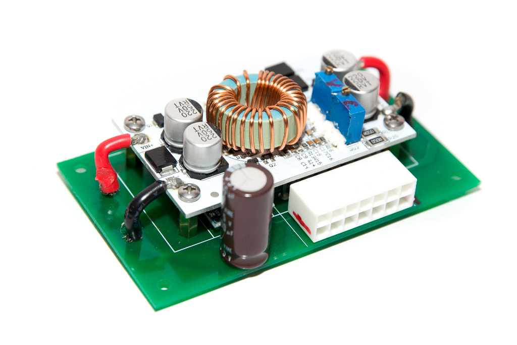
In order to reduce weight and improve the efficiency of the setup, I decided to boost LED power to 28-32 volts using the power booster from eBay. It allows me to run thinner wires (about 40 meters of AWG-20) and get heat dissipation under control.
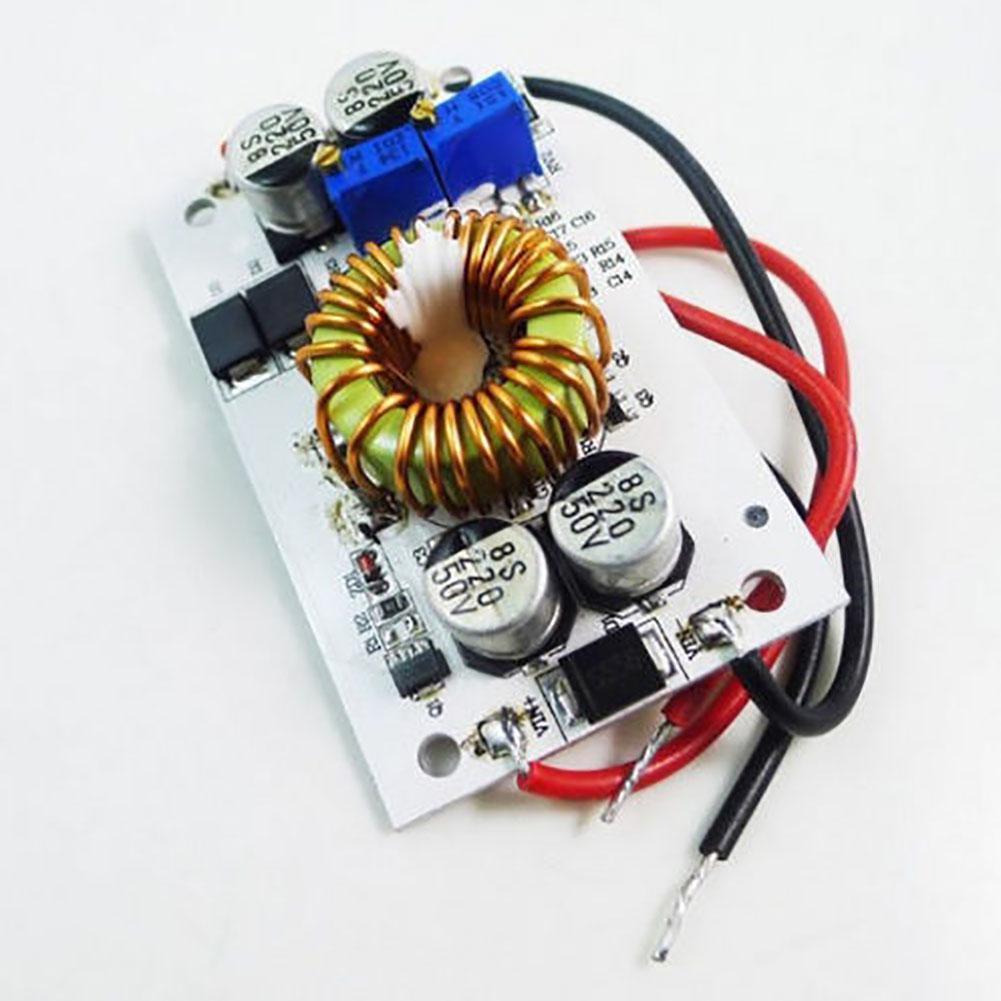
Voltage booster details:
eBay Description: DC DC Boost Converter Constant Current Mobile Power supply 250W 10A LED Driver
Input: 8.5-48V DC
Input Current: 10A (MAX)
Output: 10-50V adjustable
Output Current: 10A (MAX) 6A nominal
Output Constant Current: 0.2-8A
Switching Frequency: 150KHz
Temperature: -40 to + 85oC
Efficiency: up to 96%
Over current protection:Yes (automatic output voltage reduction at 13A)
Input Reverse Polarity Protection: Yes(5A)
Installation: 4 PCS 3mm screw holes
Dimension:70*36*18mm (2.76″x1.42″x0.71″)
Weight: 65g, aluminum-clad PCB.
Booster components:
TL494 PWM DC converter controller SOIC-16
4x 50V 220uF ele. cap.
M10100 10A 100V dual Schottky diode D-PAK (TO-252)
NCE6075k NCE Power N-CH MOSFET 60V 75A 11.5mΩ D-PAK (TO-252)
R010 current shunt resistor
10k CV 10-turns trimmer resistor
50k CC 10-turns trimmer resistor
SS54 5A 40V schottky, input reverse protection shunt.
The LED power is controlled by a simple Arduino Nano circuit driving four MOSFETs. There is a control channel for each strobe or each landing light. There are 4 programmable channels all together. The circuit diagram shows only one channel connected to D2 output. The other channel is connected to D3. The MOSFET control circuit is identical for all channels.
The light controller is pretty much an open platform that can be adjusted to any type of LED light you can think of.
PCB for the controller and most of the components are available at our Store
Connecting the controller
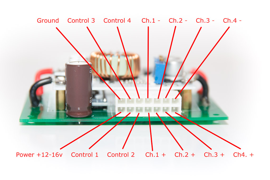
The controller connected to the lights via two wires – positive and negative. Negative wire should not be grounded!
It might look like a waste of wiring, but it is generally good idea to to run long power wires in twisted pairs rather than having one positive wire and use aircraft body to be a negative wire. It helps to reduce interference a lot. Control pins should be either hanging (not connected to anything) [off] or grounded [on]. Do not apply +12v to these pins, it will fry the Arduino board.
Use AWG18 to wire the board to +12v and Ground. For the lights wire I used AWG20. Always use aircraft grade wiring (TEFZEL)!
Parts list
| Schematics Reference | Part Name |
 Arduino Nano (Available in our Store) Arduino Nano (Available in our Store) | |
Assembly Instructions
| # | Step |
| 1. | 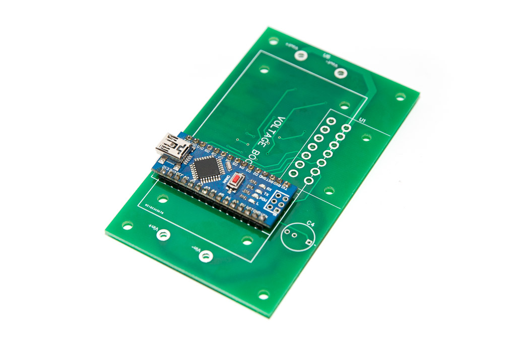 Solder the Arduino board on the PCB Solder the Arduino board on the PCB |
| 2. | 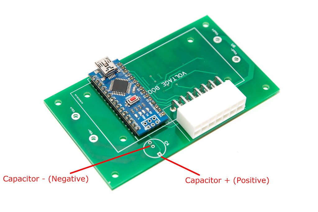 Solder the Molex connector Solder the Molex connector |
| 3. | Solder the capacitor ensuring correct orientation (see the picture above) |
| 4. |  Attach the 11mm standoffs to the PCB and then attach the Volage Booster to the standoffs. Shorten the leads as appropriate and solder them to the PCB board. Attach the 11mm standoffs to the PCB and then attach the Volage Booster to the standoffs. Shorten the leads as appropriate and solder them to the PCB board. |
| 5. | Upload the software to the Arduino board. No external power is required at this stage. USB power is enough to ensure the Arduino controller is functioning and the small LED’s at the bottom side of the PCB are blinking as required. Make the changes to the blinking pattern as desired. |
| 6. | 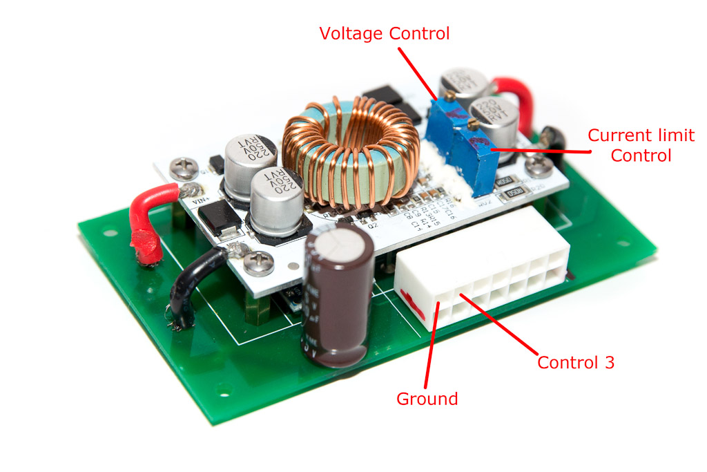 Disconnect USB and connect the external power. Disconnect USB and connect the external power.
Ground the Control 3 pin to disable blinking. Set the voltage on the Ch.4 terminal to about 30V (or whatever desired) by adjusting the Voltage Control trimpot |
| 7. | Connect the LED Light to Channel 4 and adjust the current limit.
Simply turn the Current Limiting trimpot until the brightness of the LED is not increasing anymore. |
Software
Software Download
4 Channels Strobe lights: https://github.com/ExperimentalAvionics/Strobe_Lights_4Channel_v1
Landing lights: Coming soon
Schematics
Coming soon
ToDo/FixIt
| # | Description |
Landing Lights
My original idea was to use automotive lights. They are reasonably priced ($56 for a pair), look really nice, fit my 5″ light opening in the wing very nicely and have 20W Cree LEDs in them.
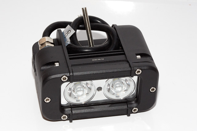
Their main disadvantage is weight – 0.67Kg – far too much for my liking.


So I decided to build my own lights using three 10W LED attached to aluminium heat sink. I bought two 150x59x25mm heat sinks from eBay for $5.60 each and cut them to 5″ to fit the mounts in the wing. I also bought six 10W LEDs for about $3 each. These particular LEDs designed to run at about 32 volts and 300mA.

The light’s weight is only 144 grams – lighter than similar light from AEROLED AeroSun, which is 227 grams. I must admit the AeroSun looks cooler. But my light cost me $15 while AeroSun would cost me almost $500 each including delivery. [Dollars are Australian. Current exchange rate is about 0.78]
Tests showed pretty good brightness of the lights and the heat sink maintained the temperature of the surface near the central LED around 62C with ambient temperature 20C. Driving the lights at 50% duty cycle (wig-wag) reduces the temperature to about 50C. Longevity of these cheap Chinese LEDs is a bit of a mystery, but for 3$ a pop I’m happy to change them from time to time.
I decided not to use any lenses on the LEDs. It would look nicer with lenses but I’d like to have a relatively wide beam of light. After all this light is to make me noticeable in the circuit, not to blind the kangaroos on the runway.
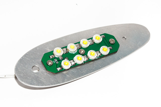
Wing-tip Strobe Lights

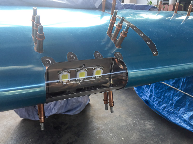
The biggest challenge of the strobe light was to find a lens to cover the LEDs. I was very close to building my own molding machine, but one day my wife pointed out that I could simply use a lens from a motorbike turn indicator (blinker). She can be right sometimes 🙂
I found a pair of clear lenses from Ducati Hypermotard for about $18. They look pretty sexy, although need to be filed a bit to lay flat of the surface.
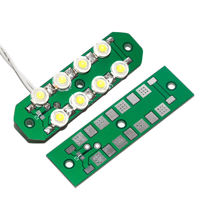
The rest was easy – I created a PCB for eight 3W LEDs connected in series. They run at about 32V with 700mA. The PCB has been built in a way that would take the heat out of LEDs and transfer it to the mounting surface. However, with the duty cycle around 10% they barely get warm.
The strobe turned out to be very bright. I like it. I’m thinking of replacing the LEDs with the 5W ones. That will be really bright.
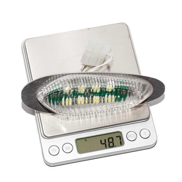
All up the strobe cost me about $40 for the pair and weight just under 50 grams each. Just to compare AeroLED Pulsar NPS is similar in brightness, weights about 200 grams (for the pair, I hope) and costs over $1100 for the pair in Australia.